Modifications reserved
Page 48/66
OPM_LPS_3UO_80K_M10_1US_V010.doc
User Manual
LP33 Series 80 & 100 UL S1
7.1.3 From Manual Bypass Q2 to normal function VFI
This procedure presupposes that the
load
is powered by the
manual bypass
switch, and:
•
The
inverter
is switched OFF;
•
The
manual bypass switch Q2
is closed (Pos. I);
•
The
output switch Q1
is open (Pos. 0);
•
The
“Battery Breaker”
of the
battery cabinet
is OFF (Pos. 0).
•
LED Alarm
blinks.
NOTE !
This procedure must not be performed if the UPS is used as
frequency converter
.
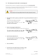
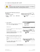
1.
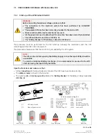
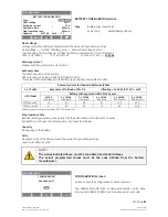
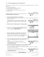
Close the output switch Q1 (Pos. I).
Load
is now supplied parallel through
automatic bypass
and
manual bypass Q2
.
The
synoptic diagram
must display the status
“
LOAD
SUPPLIED BY AUTOMATIC BYPASS AND MANUAL BYPASS
Q2
”
.
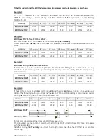
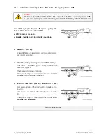
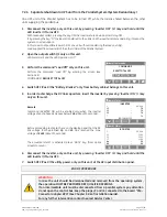
2. Switch
ON
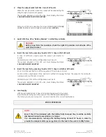
(Pos. I) the “Battery Breaker” from battery cabinet.
`
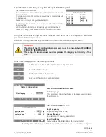
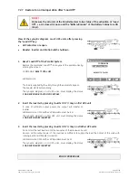
Home\Commands
COMMANDS
RESET TOTAL OFF
REQUEST TOTAL OFF
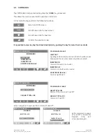
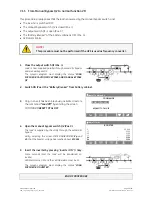
3.
Only in case it has been previously activated, restore
the command
“Load Off”
by entering the screen:
COMMANDS/
RESET TOTAL OFF
V
`
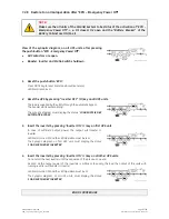
Home\Meter
BOOSTER
f :
60.0
Hz
L1 :
120
V
L2 :
120
V
L3 :
120
V
Vp :
210
V
Vn :
210
V
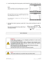
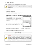
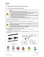
4.
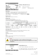
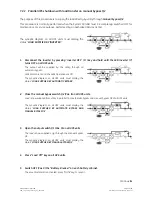
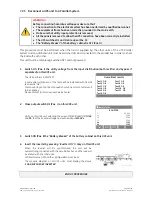
Open the manual bypass switch Q2 (Pos. 0).
The
load
is supplied by the
utility
through the
automatic
bypass
.
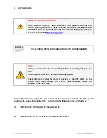
Verify, selecting the screen
METERING/BOOSTER/
Vp
and
Vn
, that the booster voltage has reached about
210 Vdc
.
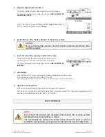
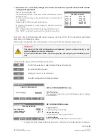
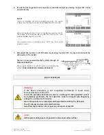
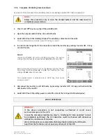
5. Insert the inverter by pressing
“
Inverter ON
”
( I ) key.
Some seconds later the
load
will be transferred on
inverter
.
LED Alarm
turns OFF and the
LED Operation
must be lit.
The
synoptic diagram
must display the status
“
LOAD
SUPPLIED BY INVERTER
”
.
END OF PROCEDURE

