Modifications reserved
Page 43/66
OPM_LPS_3UO_80K_M10_1US_V010.doc
User Manual
LP33 Series 80 & 100 UL S1
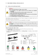
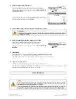
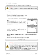
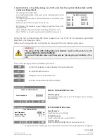
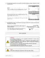
1. Switch ON (Pos. I) the utility voltage from the input distribution panel.
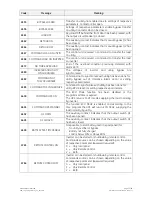
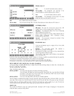
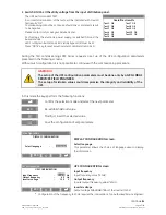
Overall test results
Test1 OK
Test7 OK
Test2 OK
Test8 OK
Test3 OK
Test9 OK
Test4 OK
Test10 OK
Test5 OK
Test11 OK
Test6 OK
The UPS performs a
SELFTEST
.
A successful termination of the tests will be indicated with Overall
test results
“OK”
.
Commissioning cannot be continued should one or more tests result
to be negative.
Please contact in this case your
Service Center
.
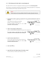
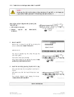
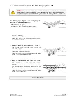
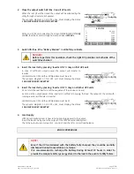
At this stage the electronic power supply is switched ON and the
buzzer sounds.
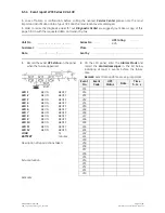
LED 1 (utility rectifier OK)
and
LED 2 (utility bypass OK)
must be lit.
Press
“MUTE”
key to reset
acoustical alarm
.
LED Alarm
remains lit.
During the first commissioning
LP33 Series
requests a set up of the UPS configuration parameters
presented in the following screens.
Without such configuration it is not possible to continue with the commissioning procedure.
WARNING !
The setup of the UPS configuration parameters must be done only by a
GE GLOBAL
SERVICES FIELD ENGINEER
.
The setup of mistaken values could compromise the integrity and reliability of the
UPS.
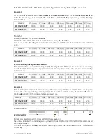
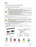
In this mode the keys perform the following functions:
Confirm the selection made and select the next parameter.
ESC
Re-establish default value.
Modify or insert the selected value.
Save the configuration of set parameters.
`
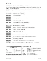
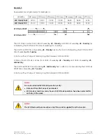
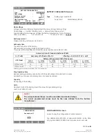
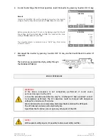
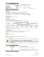
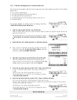
Configuration
DISPLAY CONFIGURATION
Select language
:
ENGLISH
ESC
DISPLAY CONFIGURATION screen
Select language
This parameter allows the choice of language used to display
the information.
`
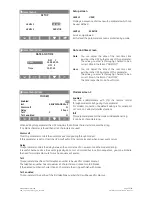
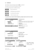
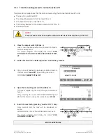
Configuration
UPS CONFIGURATION
Input frequency
:
60
Hz
Output frequency
:
60 Hz
Inverter voltage
:
120
V
ESC
UPS CONFIGURATION screen
Input frequency
Input frequency value (*60Hz).
Output frequency
Inverter output frequency value (*60Hz).
Inverter voltage
Output voltage PHASE/NEUTRAL of the inverter (120 V).
*
Configuration of the frequency to 50Hz requires the intervention of an
Authorized Service Engineer
.
Continue
►

