background image

Modifications reserved 

Page 24/66 

OPM_LPS_3UO_80K_M10_1US_V010.doc 

User Manual 

LP33 Series 80 & 100 UL S1


6  LCD SCREEN 


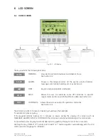
6.1  HOME SCREEN 


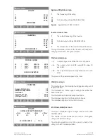
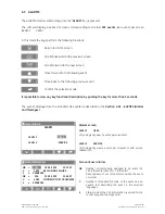
Fig. 6.1-1   LCD display 


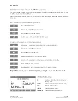
The keys perform the following functions: 


METER


METERING View 

electric 

parameters 

values and statistics of use. 

See 

Section 6.2


ALARM


ALARMS 

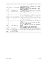
Shows in chronological order, all the events occurred (alarms, 
messages, commands, handling, etc.). See 

Section 6.3.


MUTE 

Key to reset general alarm and buzzer. 


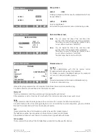
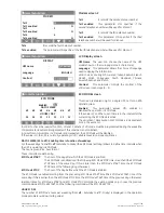
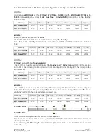
SETUP


SETUP 

Allows the user to customize some UPS functions to specific 
requirements and to view UPS identification data. See 

Section 6.4


CMDS


COMMANDS 

Allows the user to execute UPS operation commands. 

See 

Section 6.5


The 

LCD screen

, after 5 minutes of inactivity, shuts down the backlight. 

To reactivate it, press any key. 


If the keypad remains inactive for 5 minutes or longer, during the viewing of a screen such as 

MEASURES

ALARMS

SETUP

 or 

COMMANDS

, the 

LCD screen

 returns automatically to the main screen. 


It is possible to view any key functional description by pushing the key for more than 3 seconds. 


Pushing the key 

“METER” (1

st

 button)

 and 

“ALARM” (2

nd

 button)

 together automatically sets the 

LCD


communication language for “ENGLISH”. 


Содержание LP33 Series 80

Страница 1: ...m Digital Energy User Manual Uninterruptible Power Supply LP33 Series 80 100 80 100kVA 208Vac UL S1 GE Consumer Industrial SA General Electric Company CH 6595 Riazzino Locarno Switzerland T 41 0 91 85...

Страница 2: ...sumer Industrial SA All rights reserved The information contained in this publication is intended solely for the purposes indicated The present publication and any other documentation supplied with th...

Страница 3: ...rmation and describes all you need to know about the use of the UPS Thank you for choosing GE START UP AND COMMISSIONING A GE Global Services Field Engineer must perform start up and commissioning of...

Страница 4: ...needs to be installed by a licensed and knowledgeable contractor We recommend that this manual be kept next to the UPS for future references If any problems are encountered with the procedures contai...

Страница 5: ...eries 80 100 42 7 1 1 Start up of the LP33 Series 80 100 42 7 1 2 UPS shutdown with load transfer on manual bypass Q2 46 7 1 3 From Manual Bypass Q2 to normal function VFI 48 7 1 4 Complete UPS shutdo...

Страница 6: ...tenance and service work should be performed by qualified service personnel only The KNOWLEDGE and the FULLY compliance of the safety instructions and the warning contained in this manual are THE ONLY...

Страница 7: ...ttery must be disconnected during maintenance or service work This UPS contains potentially hazardous voltages Be aware that the inverter can restart automatically after the utility voltage is restore...

Страница 8: ...llowing symbols are defined WARNING if instruction is not followed injury or serious equipment damage may occur CAUTION internal parts have dangerous voltage present Risk of electric shock PE Earth GN...

Страница 9: ...N 0 OFF Q1 I ON 0 OFF F11 12 13 Fig 2 1 2 General view UPS only With front door open Q2 I ON 0 OFF Q1 I ON 0 OFF F11 12 13 Fig 2 1 3 Q1 Q2 switches and F11 12 13 fuses Fig 2 1 4 Control panel Battery...

Страница 10: ...view with open door UPS with Battery Cabinet 26 650mm BC Battery cabinet option CI Customer Interface Board option F11 12 13 Power Supply Fuses 6 1 4A 600Vac Class CC Attention only for Service purpos...

Страница 11: ...n be configured for ECO Mode permitting high operating efficiency The main typical performances of the LP33 Series system are the following VFI Voltage Frequency Independent double conversion technolo...

Страница 12: ...rom the AC input voltage Automatic Bypass The automatic bypass consists of a static semiconductor switch SSR Static Switch Relay used to provide an uninterrupted transfer of the load from inverter to...

Страница 13: ...operation When the ECO Mode is selected and the mains power is available the load is normally powered through the automatic bypass When the mains voltage is detected out of the prescribed tolerances...

Страница 14: ...s operating It is excluded only if the unit is separated from the common bus by opening its output switch Q1 Mains recovery operation As soon as the mains recovers the rectifier starts up automaticall...

Страница 15: ...applied load Fig 4 2 6 Energy flow during mains failure operation In the event of an extended mains failure before the battery is fully discharged the alarm stop operation warns the user that the UPS...

Страница 16: ...equally shared by n units connected on the output bars Should one of the parallel units trip off line the remaining n 1 units will share the load maintaining the applications protected by inverter un...

Страница 17: ...Pay attention to the following recommendations The units delivered for this functioning mode need a special parameter setting so they must be prepared in advance before the installation The installati...

Страница 18: ...ntification_GE_01 F11 12 13 kVA Output Power at Pow factor Output Freq Hz Output Voltage VAC 3W N PE Output Current A lag Series Product Year Input Freq Hz Input Voltage VAC 3W N PE Input Current A Se...

Страница 19: ...rules It does not contain CFCs chlorofluorocarbons or HCFCs hydrochlorofluorocarbons RECYCLING AT THE END OF SERVICE LIFE GE in compliance with environment protection recommends to the User that the...

Страница 20: ...UPS front top acts as the UPS user interface and comprises of the following elements Back lit Graphic Display LCD with the following characteristics Multilanguage communication interface English Germ...

Страница 21: ...e Load It is possible to activate the command Load Off using the following screen COMMANDS REQUEST TOTAL OFF See Section 6 5 Attention Load Off cannot disconnect the UPS from the Load with Q2 closed H...

Страница 22: ...ot protected by UPS or in case Q1 is open LED Operation green color When lit indicates that the UPS is functioning correctly and the load is system protected Load supplied either from inverter or from...

Страница 23: ...SWITCHES Q1 UPS output switch Q2 Manual bypass switch NOTE Do not switch ON Q1 and Q2 while Inverter is ON Q2 I ON 0 OFF Q1 I ON 0 OFF Fig 5 3 1 Q1 and Q2 switches NOTE Mains failure of long duration...

Страница 24: ...some UPS functions to specific requirements and to view UPS identification data See Section 6 4 CMDS COMMANDS Allows the user to execute UPS operation commands See Section 6 5 The LCD screen after 5...

Страница 25: ...tus at 25 LED A Indicates a load level between 26 and 50 LED A B Indicate a load level between 51 and 75 LED A B C Indicate a load level between 76 and 100 LED A B C D Indicate a load level between 10...

Страница 26: ...battery charge level Autonomy The estimated backup time with the present load Charger mode The functionality of SBM Superior Battery Management can help to reduce the battery recharging time and impr...

Страница 27: ...AL for each phase A The output current as RMS values RPA value for each UPS The output load as percentage RPA value for each UPS The source of the power supplied to the load Home Meter COUNTERS Bypass...

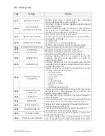
Страница 28: ...conds The events displayed are the standard GE events as described in the Section 6 3 1 EVENTS Alarms and Messages Home Alarm ALARM LEVEL 1 USER LEVEL 2 SERVICE V Alarms screen LEVEL 1 USER Chronologi...

Страница 29: ...E K4 not closed despite a closing command being done The rectifier is switched OFF 4103 K4 OPENING FAILURE K4 not open despite an opening command being done The rectifier is switched OFF 4110 RECTIFIE...

Страница 30: ...FIER CANNOT BE TURNED ON The rectifier cannot be turned on because the DC link voltage has not reached the requested value 4404 K6 CLOSING FAILURE K6 not closed despite a closing command being done Si...

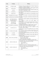
Страница 31: ...uld result below stop operation time default 3 minutes 4700 DC LOW Battery voltage is at the lowest limit Shutdown of inverter until the battery voltage reaches the value in respective parameter 4900...

Страница 32: ...ON signaling Operating mode dependent on setting of respective parameters 4164 GENERATOR OFF Customer Interface X1 11 22 received a Gen set OFF signaling Function bypass enabled dependent on setting...

Страница 33: ...bypass out of tolerance alarm 4410 or setting respective parameters 4583 COMMAND TO SYNCHRONIZE Command to synchronize with utility has been done for utility BP OK 4410 or setting respective parameter...

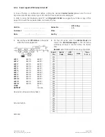
Страница 34: ...__ __ __ Series No UPS rating KVA Customer Place Date Sent by 1 Record the exact UPS status on the panel when the failure appeared 2 On the LCD panel enter the Alarms Mode and record the alarms messa...

Страница 35: ...t or modify the parameters ESC Allows to exit a selected screen without making any modification U Scrolls backward to the previous line V Scrolls forward to the next line Allows to access a value to b...

Страница 36: ...remote control through modem calls by using this parameter For modem connection the default setting is for serial port J27 or J3 on Customer Interface option Init This parameter presents the modem in...

Страница 37: ...rval for the current day the ECO Mode is active The activation deactivation of ECO Mode is indicated each time in the event list In order to check the inverter function at least 1 minute of VFI mode m...

Страница 38: ...ECO Mode during the night and week end If the ECO Mode must be enabled all nights d3 Monday to d7 Friday between 18 00 in the evening and 06 00 of the following morning and during all Saturday d1 and...

Страница 39: ...de STOP time of weekday d3 Monday has no effect as it is followed by the ECO Mode STOP time of weekday d4 Tuesday It can be without change of meaning any time between 18 00 and 23 59 Similarly the ECO...

Страница 40: ...ON INVERTER OFF BOOSTER ON Service V Commands screen 1 LAMP TEST Signaling LEDs test and buzzer test all LED should be lit and blinking and the acoustical alarm should be activated INVERTER ON Comman...

Страница 41: ...to the operations of a Parallel System NOTE Verify for correct input output cabling before connecting Utility to the UPS Open only the front door do not remove any panels Check after every step for c...

Страница 42: ...s not yet supplied by the UPS system NOTE The UPS can be started up using the Battery Supply in case the Input Utility should be unavailable To avoid an incidental Battery discharge it is recommended...

Страница 43: ...such configuration it is not possible to continue with the commissioning procedure WARNING The setup of the UPS configuration parameters must be done only by a GE GLOBAL SERVICES FIELD ENGINEER The s...

Страница 44: ...my times for lead acid batteries VRLA 2 x 72 cells Autonomy at full load at PF 0 9 U floating 164 Vdc 2 27 Vdc cell Battery with expected trickle life 10 years UPS Model 147Ah 24 blocks 2 x 147Ah 48 b...

Страница 45: ...rred on inverter LED Alarm turns OFF and the LED Operation must be lit The synoptic diagram must display the status LOAD SUPPLIED BY INVERTER 5 Load supply Your LP33 Series UPS is now running in VFI m...

Страница 46: ...nd hold until the LED inverter 7 turns OFF Load is transferred to utility by automatic bypass LED Alarm is lit and the LED Operation is Off The synoptic diagram must display the status LOAD SUPPLIED B...

Страница 47: ...The acoustical alarm is activated press MUTE key from Home screen to reset it 7 Disconnect the inverter by pressing Inverter OFF O key and hold until the LED inverter 7 turns OFF The load is now power...

Страница 48: ...the status LOAD SUPPLIED BY AUTOMATIC BYPASS AND MANUAL BYPASS Q2 2 Switch ON Pos I the Battery Breaker from battery cabinet Home Commands COMMANDS RESET TOTAL OFF REQUEST TOTAL OFF 3 Only in case it...

Страница 49: ...low 7 Vac about 30 seconds The acoustical alarm is activated press MUTE key from Home screen to reset it Home Meter BOOSTER f 60 0 Hz L1 120 V L2 120 V L3 120 V Vp 5 V Vn 5 V Before proceeding to step...

Страница 50: ...Switch shutdown Home Commands COMMANDS RESET TOTAL OFF REQUEST TOTAL OFF 1 Reset Load Off Restore the command Load Off by entering the screen COMMANDS RESET TOTAL OFF LED Alarm is lit V The load is su...

Страница 51: ...tors are open Booster Inverter and Static Switch shutdown 1 Reset the EPO key Press MUTE key to reset Alarm and Acoustical alarm LED Alarm remains lit 2 Reset the UPS by pressing Inverter OFF O key Th...

Страница 52: ...ied by the UPS Parallel System NOTE The UPS Parallel System can be started up using the Battery Supply in case the Input Utility should be unavailable To avoid an incidental Battery discharge it is re...

Страница 53: ...following screens Without such configuration it is not possible to continue with the commissioning procedure WARNING The setup of the UPS configuration parameters must be done only by a GE GLOBAL SERV...

Страница 54: ...my times for lead acid batteries VRLA 2 x 72 cells Autonomy at full load at PF 0 9 U floating 164 Vdc 2 27 Vdc cell Battery with expected trickle life 10 years UPS Model 147Ah 24 blocks 2 x 147Ah 48 b...

Страница 55: ...n must be is lit The synoptic diagram on first UPS unit must display the status LOAD SUPPLIED BY INVERTER 5 Insert the inverter by pressing Inverter ON I key on all other UPS units Do not start the ne...

Страница 56: ...be supplied by the utility through all automatic bypass LEDs Alarm are lit and the LEDs Operation are Off The synoptic diagram on all UPS units must display the status LOAD SUPPLIED BY AUTOMATIC BYPAS...

Страница 57: ...from Home screen to reset it 7 Disconnect the inverter on all UPS units by pressing Inverter OFF O key and hold until the LED Inverter 7 turns OFF The load is now powered directly by utility through...

Страница 58: ...en previously activated restore the command Load Off on any one of the units by entering the screen COMMANDS RESET TOTAL OFF V Home Meter BOOSTER f 60 0 Hz L1 120 V L2 120 V L3 120 V Vp 210 V Vn 210 V...

Страница 59: ...0 the Battery Breaker only from battery cabinet belongs to this unit 5 In order to discharge the DC link capacitors insert the inverter by pressing Inverter ON I key only on this unit Home Meter INVER...

Страница 60: ...ibution both rectifier and bypass if separated on this UPS unit Overall test results Test1 OK Test7 OK Test2 OK Test8 OK Test3 OK Test9 OK Test4 OK Test10 OK Test5 OK Test11 OK Test6 OK The UPS perfor...

Страница 61: ...erter voltage of each phase decreases below 7 Vac about 30 seconds Home Meter BOOSTER f 60 0 Hz L1 120 V L2 120 V L3 120 V Vp 5 V Vn 5 V Before proceeding to step 5 check on the display panel that the...

Страница 62: ...d by the utility through the automatic bypass The booster starts automatically The synoptic diagram on all UPS units must display the status LOAD SUPPLIED BY AUTOMATIC BYPASS 2 Insert the inverter by...

Страница 63: ...pplied by the utility through the automatic bypass The booster starts automatically The synoptic diagram must display the status LOAD SUPPLIED BY AUTOMATIC BYPASS 3 Insert the inverter by pressing Inv...

Страница 64: ...apter The 3 ph SNMP WEB plug in adapter is an Interface to the Ethernet Network and provides UPS information via the standard SNMP protocol Simple Network Management Protocol The UPS can therefore be...

Страница 65: ...ing time together with improved lifetime of the Battery As a healthy battery is essential to the performance of the UPS an automatic or manual battery test can be performed regularly to ensure failsaf...

Страница 66: ...TES FORM It is recommended to note in this section Notes with date and short description all the operations performed on the UPS as maintenance components replacement abnormal situations etc Date Desc...

Отзывы: