GE IJS51A Скачать руководство пользователя страница 24

GEH-1791  Synchronism-Check Relays  Type  LJS 

turbed. 

If 

the  examination  or  tests  indicate  that 

readjustment  is  necessary,  refer  to  Section  on 

SERVICING. 

VISUAL  INSPECTION 

Check  the  nameplate  stamping  to  insure  that 

the  Model  Number  and  rating  of  the  relay  agree 

with  the  requisition. 

Remove  the  relay  from  its  case and check that 

there  are  no  broken  or  cracked  molded  parts  of 

other  signs  of  physical  damage  and that all screws 

are  tight. 

Check  that  the  short fingers  are  in  the  correct 

location  as  indicated  in  Fig.  8  and  Fig. 

and 

that  the  auxiliary  brushes  are  properly  adjusted 

(see  Fig.  12). 

MECHANICAL  INSPEC TION 

1 .   Check  that  the  rotating  element moves  without 

noticeable friction. 

2.  Remove  the  time  dial  locking  screws  and 

check  that  the  moving  contact  just  touches 

the  stationary  contact  when  the  time  dial  is 

set  at  zero. 

The  contact  wipe  should  be 

approximately  1/32". 

3.  Check  that  the  control  spring  is  not deformed 

and  the  spring  convolutions  at  No.  5  T .D.S. 

are  reasonably  concentric . 

ELECTRICAL  TESTS 

Connect  the  relay  as  shown  in  Fig.  10  and 

check the  following: 

1 .   C heck  that  the  relay  picks  up  with  at  least 

1 1 5   volts,  60  cycle  single-phase  source  con­

nected  to both operating coils with approximately 

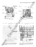
the  time  delay shown  in  Fig.  7. 

2.  Check  that  the  relay  picks  up  at a 20° closing 

angle  (or  other  closing  angle  is  used)  within 

.± 

3  degrees  when  connected  to  a  1 1 5   volt,  60 

cycle  source  with  rated voltages  on both  coils. 

Check  zero  displacement  pick  up which should 

agree  with  the  value  in  Fig.  1  within 

.± 

10 

percent. 

3.  With  both  coils  connected  to  1 1 5   volt  source 

with  zero  displacement,  check  that  pick  up 

time  agrees  with  values  given  in  Figures  4 

or  5 plus  or minus  10  percent. 

INSTALLATION  PROCEDURE 

If 

after  acceptance  tests  the  relay  is  held  in 

storage  before  shipment  to  the  job  site,  it  is 

r ecommended  that visual  and mechanical inspection 

described  under  the  section  on  ACCEPTANCE 

TESTS be  repeated before  installation. 

E LECTRICAL  TESTS 

Before  the  following  electrical  tests are made 

the  relay  should  be  in  its  case,  preferably mounted 

in its  permanent  location. 

A  typical  elementary  diagram of external  con­

nections  is  shown  in  Fig.  1 1 .  

The  "B"  contact 

of  52  in  series  with  only one  coil  circuit serves  to 

reset the  disk and  contacts  promptly after the circuit 

breaker  closes,  so  that  the  normal  delay  is avail­

able  as  soon  as  possible  in  case  the  breaker  trips 

again.  Additional  relays  (undervoltage  or reclosing) 

may  be  considered  desirable  for  prevention  of 

unlimited  reclosures  in  case of  one  wire  broken  and 

grounded or  crossed with another  phase. 

The  relay  c losing  angle  should  be  set  as 

required  for  its  permanent  location  which  would 

normally  be  20  degrees. 

Connect  the  relay  as 

shown  in  Fig.  10  and  check  that  the  relay picks  up 

at  the  proper  phase  angle plus  or  minus  3  degrees. 

If 

a  phase  angle  meter  or  a  phase  shifter  is 

not  available,  it  is  possible  to  adjust  the  relay to 

approximately  the  closing  angle  desired  by  means 

of  the  connections  and  curve  shown  in  Fig.  12A. 

In 

this  test  rated  voltage  is  held  on  one  circuit 

(studs  7-8)  and  a  reduced  voltage  is  applied to  the 

other  circuit  (studs  5-6).  The  voltage  connected 

to  studs  5-6  is  adjusted  until  the  synchronizing 

check  unit  just  closes  its  contact.  The difference 

between  the  two voltages  should agree approximately 

with  the  voltage  given  on  the  curve  shown  in  Fig. 

12A  for  the  phase  angle  used  (i.e.  24  volts for 20 

degrees  closing). 

When  using either  connections  shown  in  Fig.  10 

or  Fig.  12,  check  the  operating  time  at  0  dis­

placement  with  1 1 5   volts  on  each  coil  using  the 

time  dial  setting  of  the  permanent  location.  (See 

Fig.  7 for nominal time  delay  values. )  

PERIODIC  CHECKS  AND 

ROUTINE  MAINTENANCE 

In 

view  of  the  vital  role  of  protective  relays 

in  the  operation  of  a  power  system  it  is  important 

that  a  periodic  test  program  be  followed.  It  is 

recognized that the  interval between periodic checks 

will  vary  depending upon  environment,  type  of  relay 

and  the  user's  experience  with  periodic  testing. 

Until the  user  has  accumulated  enough  experience to 

select  the  test  interval  best  suited to  his  individual 

requirements  it  is  suggested  that  the  following 

points  be  checked  at  an interval of  from one to two 

years. 

MECHANICAL 

The  mechanical  checks  described  under  the 

section  on  ACCEPTANCE  TESTS should be repeated. 

www 

. ElectricalPartManuals 

. com 

Содержание IJS51A

Страница 1: ...Types IJS51A and IJS52A INSTRUCTIONS SYNCHRONISM CHECK RELAYS GEH 179111 GE Meter and Control 205 Great Valley Parkway Malvern PA 19355 0715 w w w E l e c t r i c a l P a r t M a n u a l s c o m ...

Страница 2: ...ENS 6 CONSTRUCTION 6 RECEIVING HANDLING AND STORAGE 6 ACCEPTANCE TESTS 7 INSTALLATION PROCEDURE 7 PERIODIC CHECKS AND ROUTINE MAINTENANCE 8 SERVICING 9 Closing Angle Adjustment 9 Time Characteristics 10 RENEWAL PARTS 10 Cover Photo 8007016 2 w w w E l e c t r i c a l P a r t M a n u a l s c o m ...

Страница 3: ... be considerably out of phase due to load transfer around the loop that is open at the breaker controlled by the relay Forms of the relay are available with a rated calibration range up to 600 but for settings over 200 consideration should be given to the resulting generator stresses at the instant of closure through existing system impedances as in any other situation involving out of phase closu...

Страница 4: ...le is considered standard however other settings may be made as indicated by the voltage phase angle characteristics shown in Figure 1 The time delay characteristics of the Type IJS relay are obtained primariy by the time dial setting The time dial controls the distance the contacts must travel before closure and hence controls the time delay At No 10 time dial setting the travel is maximum wherea...

Страница 5: ... from 0 2 up to 2 0 amperes at the minimum control voltage If this tap is used with circuits requiring more than 2 amperes there is a possibility that the 7 ohm resistance will reduce the current to so low a value that the proper current may not be obtained The 2 0 ampere tap should be used with circuits that take 2 0 amperes or more at minimum control voltage provided the current does not exceed ...

Страница 6: ...e connection plugs have been inserted The relay case is suitable for either semi flush or surface mounting on all panels up to 2 inches thick and appropriate hardware is available However panel thickness must be indicated on the relay order to ensure that proper hardware will be included For outline and drilling dimensions see Figure 15 RECEIVING HANDLING AND STORAGE These relays when not included...

Страница 7: ...tact when the time dial is set at 0 The contact wipe should be approximately 1 3211 3 Check that the control spring is not deformed and that the spring convolutions at No 5 time dial setting are reasonably concentric ELECTRICAL TESTS Connect the relay as shown in Figure 11 and check the following 1 Check that with at least 115 volts 60 cycle single phase source connected to both operating coils th...

Страница 8: ...o studs 5 6 is adjusted until the synchronizing check unit just closes its contact The difference between the two voltages should agree approximately with the voltage given on the curve shown in Figure 14 for the phase angle used i e 24 volts for 200 closing When using connections shown in either Figure 11 or Figure 13 check the operating time at 0 displacement with 115 volts on each coil using th...

Страница 9: ...hould be approximately centered between the poles of the U magnet and drag magnet ELECTRICAL ADJUSTMENTS Closing Angle Adjustment Connect the relay as shown in Figure 11 To make an accurate adjustment of the closing angle a phase shifter and phase angle meter are required along with a means for voltage control Two adjustments are necessary for obtaining a desired closing angle adjustable resistor ...

Страница 10: ...ficient quantities of renewal parts should be kept in stock for the prompt replacement of any that are worn broken or damaged When ordering renewal parts address the nearest Sales Office of the General Electric Company Specify the name of the part wanted quantity required and complete nameplate data including the serial number of the relay If possible give the General Electric requisition number o...

Страница 11: ...nts with Rated Voltage Maintained on One Circuit CONNECTING PLUG AUXIL IARY BRUSH BLOCK TERMINAL BLOCK SHORTING BAR NOTE AF TER ENGAG ING AUXIL IARY BRUSH CONNECTING PLUG TRAVELS 1 4 INCH BEFORE ENGAG ING THE MAIN BRUSH ON THE TERMINAL BLOCK Figure 2 8025039 Cross Section of Drawout Case Showing Position of Auxiliary Brush and Shorting Brush 11 w w w E l e c t r i c a l P a r t M a n u a l s c o m...

Страница 12: ...ic of 60 Cycle Relay 12IJS51A1 With Rated Voltage On Both Circuits With 10 Time Dial Settings Figure 4 8007013 Type IJS51A Relay Unit in Cradle Rear View 9 1 8 1 u J en _ 7 w I 6 0 0 0 0 0 0 50 en 0 z 8 4 w en w 3 I z 2 w a 0 0 0 0 10 0 I i I I c I i lfzo CLOSING ANGLE i I J30 CLOSING ANGLE i I I I j 1 l I u 4 0 gw G v 1 v I i f I f i 1 v J I I v I __ _ V 6oo CLOSING ANGLE i J I 50 40 30 20 10 0 1...

Страница 13: ...age on Both Circuits With 10 Time Dial Settings Sl OUND _j SHADING COILS t l I 1 2 l l 5 6 l 7 I8 OOT REST SHORT F I NGER Figure 9 6305898 3 Internal Connec tions For Type IJS51A Relay Front View I 20 16 12 V 0 0 u I II 8 v 4 v ov 2 i 1 I v I v I v I I I 4 6 TilliE DIAl SETTING i v v 8 10 Figure 8 6400150 2 Operating Time of Type IJS Relay With 200 Closing Angle Time at oo 115 Volts 60 Cycles on B...

Страница 14: ... G CIRCUIT OF oi Hl DEVICE FUNCTION NUMBERS 25 SYNCHRONISM CHECK RE LAY TYPE IJS 278 BUS UNDERVOLTAGE RELAY TYPf HGA14AR 27L LINE UNDERVOLTAGE RELAY TYPF fjGA14AR 52 POWER CIRCUIT BREAKER 52C S CONTROL S ITCH TYPE SB 1 Figure 12 6209561 5 Typical Elementary Diagram of External Connections Type IJS Relays 100 l 90 v i 80 70 I i 0 u 7 t 60 c I __ z I 0 u 50 I 0 _ 1 40 r f 7 I I f __ ll 30 i 20 0 N 7...

Страница 15: ...6MM 4 375T 111MM _L__ l I CUTbUT I I I I I 5 687 144MM 112MM j_ 8 81 223M 2 M I 2 18 r 5MM I I PANEL I FOR PANEL DRILLING SEMI FLUSH MOUNTING FRONT VIE 718 1 8MM TYPICAL DIM 3 0 I 76MM 3 4 DRILL 10 HOLES 19MM PANEL DRILLING FOR SURFACE MOUNTING FRONT VIEW 5 16 18 STUD INCHES MM VIEW SHOWING ASSEMBLY OF HARDWARE FOR SURFACE MTG ON STEEL PANELS Figure 15 6209271 8 Outline and Panel Drilling Dimensio...

Страница 16: ...ST 9 93 200 16 Meter and Control Business Department General Electric Company Protection and Control 205 Great Valley Parkway Malvern Pennsylvania 19355 0715 w w w E l e c t r i c a l P a r t M a n u a l s c o m ...

Страница 17: ...INSTRUCTIONS GEH 1791 E Supersedes GEH 1791 D SYNCHRONISM CHECK RELAYS TYPES IJS51A AND IJS52A GENERAL fj ELECTRIC w w w E l e c t r i c a l P a r t M a n u a l s c o m ...

Страница 18: ...w w w E l e c t r i c a l P a r t M a n u a l s c o m ...

Страница 19: ...llel with those of the GES or GXS The IJS is not adaptable to applications in volving continuous loading of the contact circuit since contact welding may result even with contact loadings that are low in relation to the interrupting capacity of the contacts The control should be designed to energize the IJS coils when synchronism is to be checked and to permit the IJS contacts to be the last to co...

Страница 20: ...it energized varies from 3 seconds on the 20 degree setting to 6 seconds on the 6 0 degree setting at the 10 TDS The Model 12IJS51A3 and 12IJS52A7A relays which are designed for use where the closing angle greater than 20 degrees is required provides 20 seconds delay at the 40 degree closing angle setting as shown in Fig 5 It may be adjusted to other closing angles between 20 and 60 degrees with c...

Страница 21: ...Type IJS51A Relay Unit In Cradle Rear View z 9 8 1 w _ 7 Cl Cl z 0 4 u w 3 1 z 2 w 0 0 I 0 I i i 0 0 t t 0 I r I o I l r 0 1 r 0 r r r TTI i I t __j_ ll I I 1 I i I 1 I i i li I i l c u20 CLOSING ANGLE t I I 1 r 1 30 CLOSING ANGLE i lJ I v J I v l _J I I I I I 40 CLOSING ANGLE I i I I I II i I v T I I I H vv l 600 jI I j j J I V CLOSING I ANGLE I I i I I i 50 40 30 20 10 0 10 20 30 40 50 PHASE ANG...

Страница 22: ... SHADING_j l t COILS 1 l I l 1 s v i I 6 TOP RfST l l i l8 BOT REST SHORT FINGER it 8 6305ScJ8 3 Intt mal Connections Fo r Type LTS lA Relay Front View V 0 z o VJ I w 20 1 1 c I f I I lb r 1 i 1 I 12 I r t I I I I 4 rr l t t A 1 I I r J I 1 I _____J_ 4 t r _j I I I I I j tT j I 4 6 10 TIME QiAL SUTING Fig 7 6400150 2 Operatine I ime o Type IJS Relay With 2JO Closing Angle Time At 0 115 Volts 60 Cy...

Страница 23: ...esired To do this the relay is first disconnected by removing the connection plug which completes the electrical connections between the case blocks and the cradle block To test the relay in its case this connection block can be replaced by a test plug The cover which is attached to the front of the relay case contains an inter lock arm which prevents the cover from being replaced until the connec...

Страница 24: ...tion A typical elementary diagram of external con nections is shown in Fig 11 The B contact of 52 in series with only one coil circuit serves to reset the disk and contacts promptly after the circuit breaker closes so that the normal delay is avail able as soon as possible in case the breaker trips again Additional relays undervoltage or reclosing may be considered desirable for prevention of unli...

Страница 25: ...C H E C K R E L A Y T Y P E I J I 2 7 8 BUS U N O E RV O L T AGE R E L A Y T Y PF H A14AR 2 7 L L r N E U N OERVO L T A G E R E L A Y r T Y P flGA 4A l 5 2 POW E R C I RC U I T B R E A KE R 5 Z C S CO N T RO L W I TC H T Y P E 58 l Fig 11 6209561 4 Typical Elementary Diagram Of External Connections Type IJS Relays 100 T I 90 1 80 70 u I 60 1 II 1 I 0 u 50 1 I 5 1 4 0 I l 7 1 3 0 1 f7 I I 20 i 10 I...

Страница 26: ...en the poles of the U magnet and drag magnet ELECTRICAL ADJUSTMENTS Closing Angle Adjustment Connect the relay as shown in Fig 10 To make an accurate adjustment of the closing angle a phase shifter and phase angle meter are required along with a means for voltage control Two adjustments are necessary for obtaining a desired closing angle The right hand adjustable resistor at the top of the frame p...

Страница 27: ...12 223M M 1 5 M M DRI LL El 2 H OLES CUTOUT M AY R EPLACE D R ILLED H OLES O PT I ONAL 2 M M 1 1 6 __ L 7 1 ts Tt tttl t S t3 VIEW SHOWING t8 t A t A ASSEME Y OF HARDwA RE FOR SU RFACE MTG 0 N STEEL PA N EL5 PANEL DRIWNG F SEM J FWSH MOUN TI NG t F RONT VIE W DR I L L 1 0 HOLES 19M M PANEL ORI LUNG FOR 9JRFACE OUNTI NG TF RONT V IE W F i g 14 6 2092 7 1 6 Ou tl i ne And Pa ne l Dr i l l i ng Dimen...

Страница 28: ...N ERA L ELECT R I C COMPANY P O W E R SYST E M S M A N A GEMENT BU SINESS DEPT P HILADELPHIA P A 1 91 4 2 G E N E R A L f j E L E C T R I C 5 80 1 0 6 5 w w w E l e c t r i c a l P a r t M a n u a l s c o m ...

Отзывы: