

CHAPTER 4: INTERFACES
G500 SUBSTATION GATEWAY INSTRUCTION MANUAL
GE INFORMATION
45
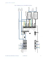
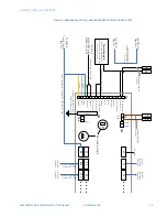
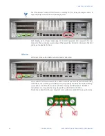
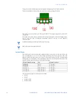
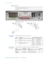
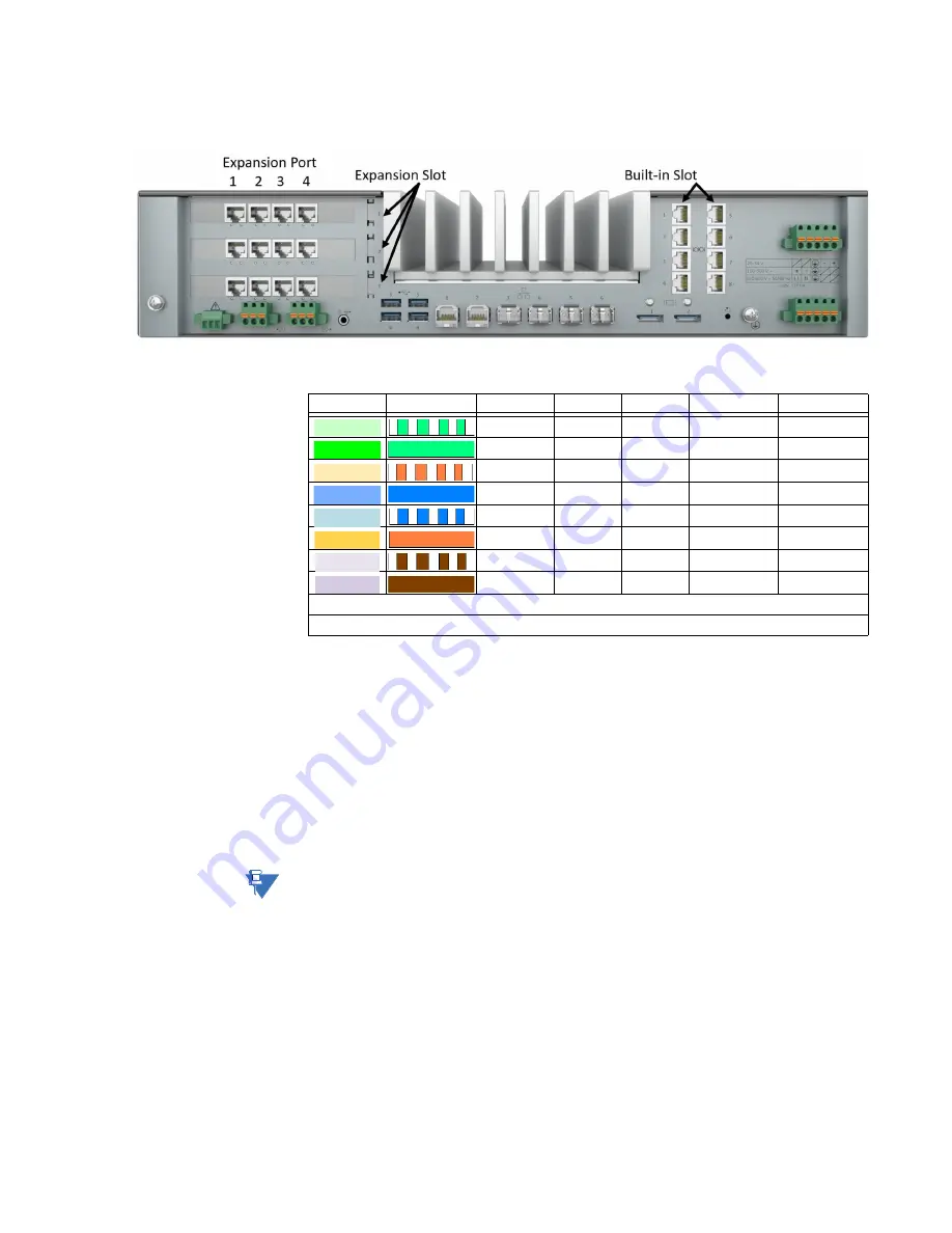
For every port an Rx Termination Resistor of 120 Ohms can be enabled through the
software interface. This termination persists even when power is lost.
The pin assignment of the Serial Interfaces is dependent on the operation mode selected
for the interface:
Rx-
Rx-
D-
Rx+
Rx+
D+
Tx-
Tx-
-
GND
GND
GND
IRIG-B*
IRIG-B*
IRIG-B*
Tx+
Tx+
-
VCC**
VCC**
VCC**
-
-
-
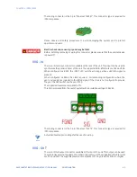
The VCC (Pin 7) is available on port 4 and port 8 from the Built-in slots and port 4 of each
PCIe Expansion card installed in Expansion slots 1, 2 and 3. It is a 12V power output that is
limited to 6W. If a higher load is applied to the output the output shuts down.
The IRIG-B (Pin 5) is available on ports 1 through 8 of the Built-in slots and is not available
on any of the ports from the Expansion slots. The IRIG-B signal is a copy of the IRIG-B time
signal output on the rear of the system. This output can be used to synchronize external
equipment or other units to this unit. The supported levels are compliant to TTL by a load
of 120Ohm or higher. It is current limited and protected against damage by short to GND
(Pin 4).
For interconnection of 2 G500 in 485-2W mode a standard 1:1 patch cable can be used.
For all other modes a standard crossover is suitable.
NOTE
Shielded twisted pair cables shall be used for wiring.
G500 v1.0 does not support IRIG-OUT.
High-voltage
installations
To provide higher EMC immunity and maintain CE Mark radiated emission compliance, the
serial cables used for permanent RS-232 and RS-485 connections must comply with the
following requirements:
•
Cables must be shielded
•
D-type connector covers must provide EMC shielding (e.g. metalized plastic or die cast
metal covers).
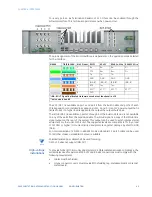
EIA568
TIA/EIA 568A
RJ45 Pinout RS232
RS422
RS485 4-Wire RS485 2-Wire
1
Rx
2
CTS
3
Tx
4
GND
5
IRIG-B*
6
RTS
7
VCC**
8
DCD
*IRIG-B OUT Signal is allocated Hardware wise but not functional in v1.0
**only on port 4 and 8
Содержание G500
Страница 6: ...6 GE INFORMATION G500 SUBSTATION GATEWAY INSTRUCTION MANUAL TABLE OF CONTENTS ...
Страница 16: ...16 GE INFORMATION G500 SUBSTATION GATEWAY INSTRUCTION MANUAL CHAPTER 1 INTRODUCTION ...
Страница 36: ...36 GE INFORMATION G500 SUBSTATION GATEWAY INSTRUCTION MANUAL CHAPTER 3 INSTALLING THE G500 ...
Страница 64: ...64 GE INFORMATION G500 SUBSTATION GATEWAY INSTRUCTION MANUAL CHAPTER 4 INTERFACES ...
Страница 72: ...72 GE INFORMATION G500 SUBSTATION GATEWAY INSTRUCTION MANUAL CHAPTER 5 INDICATORS ...
Страница 77: ...CHAPTER 6 SPECIFICATIONS G500 SUBSTATION GATEWAY INSTRUCTION MANUAL GE INFORMATION 77 ...
Страница 78: ...78 GE INFORMATION G500 SUBSTATION GATEWAY INSTRUCTION MANUAL CHAPTER 6 SPECIFICATIONS ...
Страница 80: ...80 GE INFORMATION G500 SUBSTATION GATEWAY INSTRUCTION MANUAL CHAPTER 6 SPECIFICATIONS ...
Страница 85: ...G500 SUBSTATION GATEWAY INSTRUCTION MANUAL GE INFORMATION 85 G500 Substation Gateway Appendix B cUL cUL ...
Страница 86: ...86 GE INFORMATION G500 SUBSTATION GATEWAY INSTRUCTION MANUAL APPENDIX B CUL ...
Страница 88: ...88 GE INFORMATION G500 SUBSTATION GATEWAY INSTRUCTION MANUAL APPENDIX C WARRANTY ...
Страница 92: ...92 GE INFORMATION G500 SUBSTATION GATEWAY INSTRUCTION MANUAL REVISION HISTORY ...


