

CHAPTER 3: INSTALLING THE G500
G500 SUBSTATION GATEWAY INSTRUCTION MANUAL
GE INFORMATION
27
Inrush current
The inrush current is typically 13A when powering up.
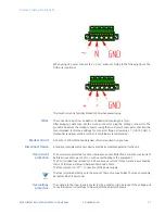
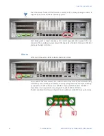
Reverse polarity
protection
The product is equipped with built-in reverse polarity protection. If + and - are swapped the
unit will not power-up and harm to neither the power supply nor the unit will occur.
Overcurrent
protection
The overcurrent protection function interrupts an uncontrolled fault current or overcurrent
before serious damage can occur, such as overheating of the equipment.
The PSU included fuse is rated for 16A continuous current. If that current is exceeded by
factor 10 the fuse will blow in between 10ms and 100ms.
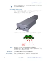
The fuse is placed in”-“connection of the power supply.
NOTE
The fuse is soldered directly onto the product. There is no fuse holder. The fuse should only
be replaced by GE personnel.
Overvoltage
protection
The voltage to the inner loads is protected by a varistor. High increase of the voltage will
cause the internal current fuse to blow and/or the Varistor to break.
NOTE
The varistor is soldered directly onto the product. There is no fuse holder. The varistor
should only be replaced by GE personnel.
Power-On Self-Test (POST)
Each time the G500 boots up it must pass the POST (Power-On Self-Test). The following
tests make up the POST:
•
CPU must exit the reset status and be able to execute instructions
•
SPI Flash ROM and NVRAM is accessible
•
Checksum must be valid
•
CMOS is readable, CMOS checksum must be valid
•
CPU must be able to access all forms of memory such as the memory controller,
memory bus, and memory module
•
The first 64 KB of memory must be operational and must be capable of holding the
POST code
•
I/O bus / controller must be accessible
•
I/O bus must be able to write / read from the video subsystem and be able to access
all video RAM
If the G500 does not pass one or more of the above tests, the board will fail the POST and
display a hexadecimal value on the lower right corner of the screen. Please contact GE’s
Grid Solution support with the hexadecimal code in this case.
Super Capacitor
The G500 does not include a battery. The real-time clock is buffered via a super capacitor
for at least 7 days of no connection to power. After this time, it may be reset to 12:00 AM,
01-10-2000 at start-up and therefore necessary to readjust the system time.
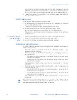
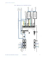
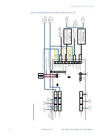
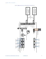
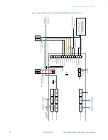
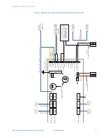
G500 system redundancy
A redundant G500 setup allows a secondary G500 to automatically take over operations
from a paired G500 unit that has failed.
Содержание G500
Страница 6: ...6 GE INFORMATION G500 SUBSTATION GATEWAY INSTRUCTION MANUAL TABLE OF CONTENTS ...
Страница 16: ...16 GE INFORMATION G500 SUBSTATION GATEWAY INSTRUCTION MANUAL CHAPTER 1 INTRODUCTION ...
Страница 36: ...36 GE INFORMATION G500 SUBSTATION GATEWAY INSTRUCTION MANUAL CHAPTER 3 INSTALLING THE G500 ...
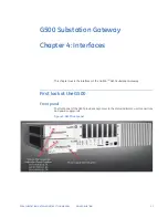
Страница 64: ...64 GE INFORMATION G500 SUBSTATION GATEWAY INSTRUCTION MANUAL CHAPTER 4 INTERFACES ...
Страница 72: ...72 GE INFORMATION G500 SUBSTATION GATEWAY INSTRUCTION MANUAL CHAPTER 5 INDICATORS ...
Страница 77: ...CHAPTER 6 SPECIFICATIONS G500 SUBSTATION GATEWAY INSTRUCTION MANUAL GE INFORMATION 77 ...
Страница 78: ...78 GE INFORMATION G500 SUBSTATION GATEWAY INSTRUCTION MANUAL CHAPTER 6 SPECIFICATIONS ...
Страница 80: ...80 GE INFORMATION G500 SUBSTATION GATEWAY INSTRUCTION MANUAL CHAPTER 6 SPECIFICATIONS ...
Страница 85: ...G500 SUBSTATION GATEWAY INSTRUCTION MANUAL GE INFORMATION 85 G500 Substation Gateway Appendix B cUL cUL ...
Страница 86: ...86 GE INFORMATION G500 SUBSTATION GATEWAY INSTRUCTION MANUAL APPENDIX B CUL ...
Страница 88: ...88 GE INFORMATION G500 SUBSTATION GATEWAY INSTRUCTION MANUAL APPENDIX C WARRANTY ...
Страница 92: ...92 GE INFORMATION G500 SUBSTATION GATEWAY INSTRUCTION MANUAL REVISION HISTORY ...