


CHAPTER 3: INSTALLING THE G500
G500 SUBSTATION GATEWAY INSTRUCTION MANUAL
GE INFORMATION
23
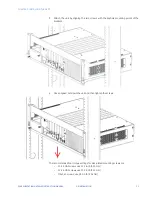
NOTE
The spacing specifications for air circulation are based on the worst-case scenario for
operation at the maximum specified ambient temperature.
If the spacing specifications for air circulation cannot be adhered to, then the maximum
specified temperatures cannot be guaranteed.
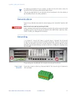
General advice
Please observe all safety procedures to avoid damaging system and protect operators and
users.
Electric shock can cause injury and may be fatal.
Before installing or removing any board, please ensure that the system power and external
supplies as well as power to devices connected to the ALARM Relay output have been
turned off and/or are unplugged from the device.
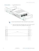
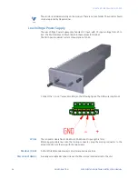
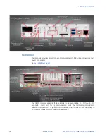
Grounding
It is required to connect the chassis to ground using at minimum the M5 ground
connection screw in point located near the G500 power supply. The second screw in point
can also be connected to ground. For proper connection, the recommended tool torque
settings for ground terminal screws are 18 in-lb [2.0 Nm]. A Phillips (#1) screwdriver tip is
recommended.
The grounding wire should be AWG 12 or lower and not longer than 1 meter.
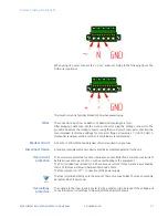
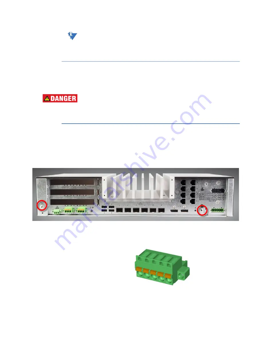
Power input
connector
The mating connector is the 5-pin “Phoenix 1942293”. This connector type is required for
IP30 compliance.
Содержание G500
Страница 6: ...6 GE INFORMATION G500 SUBSTATION GATEWAY INSTRUCTION MANUAL TABLE OF CONTENTS ...
Страница 16: ...16 GE INFORMATION G500 SUBSTATION GATEWAY INSTRUCTION MANUAL CHAPTER 1 INTRODUCTION ...
Страница 36: ...36 GE INFORMATION G500 SUBSTATION GATEWAY INSTRUCTION MANUAL CHAPTER 3 INSTALLING THE G500 ...
Страница 64: ...64 GE INFORMATION G500 SUBSTATION GATEWAY INSTRUCTION MANUAL CHAPTER 4 INTERFACES ...
Страница 72: ...72 GE INFORMATION G500 SUBSTATION GATEWAY INSTRUCTION MANUAL CHAPTER 5 INDICATORS ...
Страница 77: ...CHAPTER 6 SPECIFICATIONS G500 SUBSTATION GATEWAY INSTRUCTION MANUAL GE INFORMATION 77 ...
Страница 78: ...78 GE INFORMATION G500 SUBSTATION GATEWAY INSTRUCTION MANUAL CHAPTER 6 SPECIFICATIONS ...
Страница 80: ...80 GE INFORMATION G500 SUBSTATION GATEWAY INSTRUCTION MANUAL CHAPTER 6 SPECIFICATIONS ...
Страница 85: ...G500 SUBSTATION GATEWAY INSTRUCTION MANUAL GE INFORMATION 85 G500 Substation Gateway Appendix B cUL cUL ...
Страница 86: ...86 GE INFORMATION G500 SUBSTATION GATEWAY INSTRUCTION MANUAL APPENDIX B CUL ...
Страница 88: ...88 GE INFORMATION G500 SUBSTATION GATEWAY INSTRUCTION MANUAL APPENDIX C WARRANTY ...
Страница 92: ...92 GE INFORMATION G500 SUBSTATION GATEWAY INSTRUCTION MANUAL REVISION HISTORY ...


