

CHAPTER 4: INTERFACES
G500 SUBSTATION GATEWAY INSTRUCTION MANUAL
GE INFORMATION
43
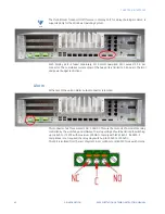
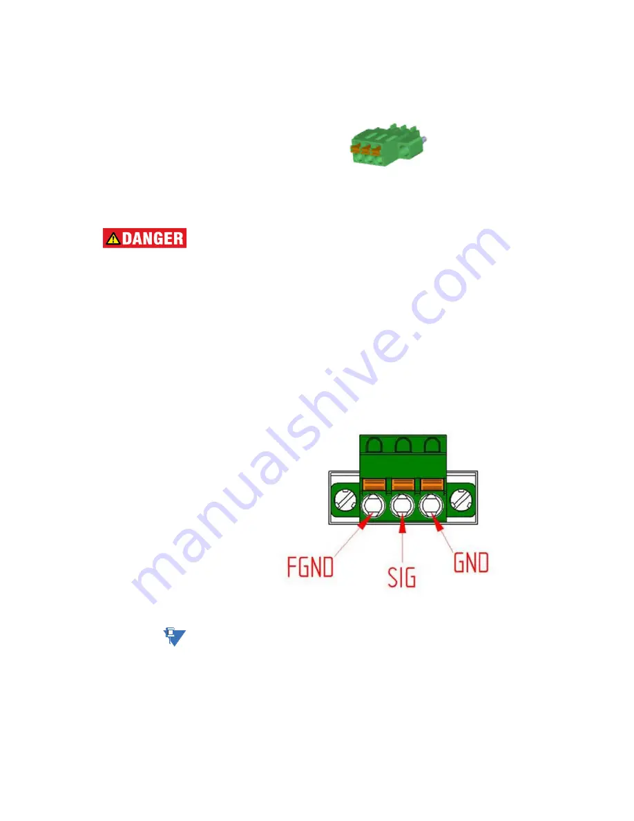
The mating connector is the 3-pin “Phoenix 1748367”. This connector type is required for
IP30 compliance.
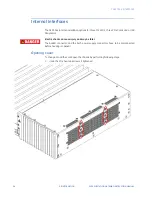
Please observe all safety procedures to avoid damaging the system and to protect
operators and users.
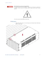
Electric shock can cause injury and may be fatal.
Before installing, removing or wiring this connector, please ensure that the external device
is power off.
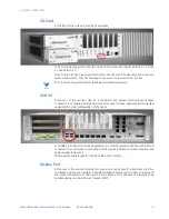
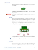
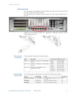
IRIG – IN
There is a IRIG-B input connector available at the rear of the unit. This input can be used to
synchronize the precision timer of the unit. The supported IRIG-B formats are 002 and 006.
When configured as B002, the INPUT LED will show Orange when valid IRIG signal is
present.
When configured as B006, the clock requires a corresponding configuration where the
year and quality are included in the IRIG-B signal. If the clock is not configured to provide
the year the G500 will show the year 2000.
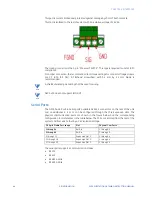
The supported levels are compliant to TTL.
This Port is isolated from the rest of system with an isolation voltage of 2kV AC.
The mating connector is the 3-pin “Phoenix 1732975”. This connector type is required for
IP30 compliance.
NOTE
A shielded twisted pair cabling shall be used for wiring.
IRIG - OUT
There is a IRIG-B output connector available at the rear of the unit. This output can be used
to synchronize external equipment or other units to this unit. The supported IRIG-B formats
are 002 and 006. The supported levels are compliant to TTL by a load of 25Ohm or higher.
Содержание G500
Страница 6: ...6 GE INFORMATION G500 SUBSTATION GATEWAY INSTRUCTION MANUAL TABLE OF CONTENTS ...
Страница 16: ...16 GE INFORMATION G500 SUBSTATION GATEWAY INSTRUCTION MANUAL CHAPTER 1 INTRODUCTION ...
Страница 36: ...36 GE INFORMATION G500 SUBSTATION GATEWAY INSTRUCTION MANUAL CHAPTER 3 INSTALLING THE G500 ...
Страница 64: ...64 GE INFORMATION G500 SUBSTATION GATEWAY INSTRUCTION MANUAL CHAPTER 4 INTERFACES ...
Страница 72: ...72 GE INFORMATION G500 SUBSTATION GATEWAY INSTRUCTION MANUAL CHAPTER 5 INDICATORS ...
Страница 77: ...CHAPTER 6 SPECIFICATIONS G500 SUBSTATION GATEWAY INSTRUCTION MANUAL GE INFORMATION 77 ...
Страница 78: ...78 GE INFORMATION G500 SUBSTATION GATEWAY INSTRUCTION MANUAL CHAPTER 6 SPECIFICATIONS ...
Страница 80: ...80 GE INFORMATION G500 SUBSTATION GATEWAY INSTRUCTION MANUAL CHAPTER 6 SPECIFICATIONS ...
Страница 85: ...G500 SUBSTATION GATEWAY INSTRUCTION MANUAL GE INFORMATION 85 G500 Substation Gateway Appendix B cUL cUL ...
Страница 86: ...86 GE INFORMATION G500 SUBSTATION GATEWAY INSTRUCTION MANUAL APPENDIX B CUL ...
Страница 88: ...88 GE INFORMATION G500 SUBSTATION GATEWAY INSTRUCTION MANUAL APPENDIX C WARRANTY ...
Страница 92: ...92 GE INFORMATION G500 SUBSTATION GATEWAY INSTRUCTION MANUAL REVISION HISTORY ...


