


3-1
Installation Environment
Install the drive in an indoor location that meets the following
requirements:
— The ambient temperature is between -10
°
C and +50
°
C
(+14
°
F to +122
°
F). (Remove the ventilation cover when
the temperature e40
°
C [+104
°
F].)
— The relative humidity is between 20% and 90%. Avoid
any location subject to condensation, freezing, or where
the drive would come in contact with water.
— Do not install in any location subject to direct sunlight,
dust, corrosive gas, inflammable gas, or oil mist.
— The drive should be installed at an elevation below
1000 meters (3281 feet). Installation above 1000
meters (3300 feet) will need to be derated 1% per 333
feet.
Example:
5 Hp, 460 VAC, output current 9 amps. Application
altitude 3900 feet.
% derate = x 1% = 1.8%
(9 amps) x
= 8.84 amps derated
output current.
Motor derate may also be required, contact motor
manufacturer.
— Vibration should be less than 0.6G.
Installation Mounting Clearance
CAUTION:
Because the ambient temperature greatly
affects drive life and reliability, do not install the drive in any
location that exceeds the allowable temperatures.
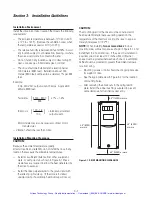
— Install at a sufficient distance from other equipment,
walls, or wiring ducts as shown in Figure 3-1 (these
clearances are required to allow the heat generated by
the drive to escape).
— Install the drive perpendicular to the ground and with
the lettering right side up. (If the drive is installed
upside-down or horizontally, heat build-up will occur.)
Section 3: Installation Guidelines
3900 - 3300
333
( )
100 - 1.8
100
( )
CAUTION:
The mounting wall for the drive must be constructed of
heat resistant material because during operation, the
temperature of the Inverter's cooling fins rises to approxi-
mately 90 degrees C (194
°
F).
NOTE:
When installing
two or more drives
in close
proximity, allow sufficient space as shown in Figure 3-1 and
install them in a horizontal row. If they must be installed in
a vertical column, at least 19.7 inches (50cm) internal
space must be provided between each one or a ventilation
baffle should be provided to prevent the ambient tempera-
ture from rising.
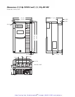
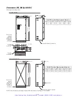
— Mounting screws or bolts should be of appropriate size
for weight of drive.
— See the appropriate view in Figure 3-2 for the location
of mounting holes.
— After removing the knockouts in the wiring lead in
plate, install the rubber bushings supplied to prevent
cable damage and to minimize dust entry.
Figure 3-1. DRIVE MOUNTING CLEARANCE
2.0” (5 CM)
or more
4.8” (12CM) or more
4.8” (12CM) or more
2.0” (5 CM)
or more
Artisan Technology Group - Quality Instrumentation ... Guaranteed | (888) 88-SOURCE | www.artisantg.com
Содержание Fuji Electric AF-300ES
Страница 32: ...3 16 Notes Artisan Technology Group Quality Instrumentation Guaranteed 888 88 SOURCE www artisantg com ...
Страница 55: ...5 9 Notes Artisan Technology Group Quality Instrumentation Guaranteed 888 88 SOURCE www artisantg com ...
Страница 58: ...5 12 Notes Artisan Technology Group Quality Instrumentation Guaranteed 888 88 SOURCE www artisantg com ...
Страница 96: ...7 4 Notes Artisan Technology Group Quality Instrumentation Guaranteed 888 88 SOURCE www artisantg com ...
Страница 122: ...10 6 Notes Artisan Technology Group Quality Instrumentation Guaranteed 888 88 SOURCE www artisantg com ...
Страница 134: ...12 6 Notes Artisan Technology Group Quality Instrumentation Guaranteed 888 88 SOURCE www artisantg com ...