11
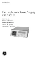
Electrophoresis Power Supply EPS 3501 XL User Manual 18-1130-22 Edition AD
IT
ALIANO
ESP
AÑOL
DEUT
CH
FRANCE
ENGLISH
PAUSE CONTINUE
Puts the instrument in PAUSE mode and switches off the voltage. The display shows the
status of the run at the time the key was pressed. PAUSE CONTINUE only operates in
RUN mode. Time, integrated voltage and integrated current are retained. In the pause
mode, SET ENTER can be used to make changes in the program. Return to RUN mode by
pressing PAUSE CONTINUE or by pressing RUN.
STOP
Stops the run and puts the instrument in END mode. The voltage is switched off and the
end parameters are displayed. Switch between time, integrated voltage and integrated
current by pressing
/
. A run cannot be continued after pressing STOP. Press RUN to
run the same method again or press SET ENTER to choose another program, program a
new method or make changes in an existing method.
INSERT DELETE
Press INSERT DELETE to insert or delete a phase in a program. This function is activated
in SET mode. Note that a program must be completed by answering YES to the question
“Last Phase?” in SET mode or by pressing EXIT before you can use INSERT DELETE.
MORE
Places program in MORE mode. Gives access to some special functions. These include:
COPY: Copying a program.
CLEAR: Clearing a program
SETUP: Disabling the start current check.
MORE mode cannot be activated in RUN or PAUSE mode. Leave MORE by pressing EXIT.
EXIT
Stops the execution of an operation, such as the entry of a value. Only values/units that
have already been confirmed by SET ENTER are retained when EXIT is pressed. Note that
if a phase contains zeros when pressing EXIT, that phase will be deleted.
Returns the instrument to the mode that was left or to the start position in SET.
4.1.3 Output sockets
There are two sets of output sockets to allow two electrophoresis units to be connected
and run at the same time, see Fig 1 inside front cover. The voltage output is 0–3500 V.
The negative output socket gives between 0 and –1750 V and the positive gives between
0 and +1750 V.
4.2 Rear panel
The rear panel is shown in Fig 2, see inside front cover. On the rear panel there is:
1. A mains switch. Press in
I
to switch on the power to the power supply. Press
O
to
switch off the power.
2. A socket for the mains cable.
3. A switch for voltage range. The left position corresponds to 100–120 V and the right
to 220–240 V.
4. Fan vents.
exit
Insert
delete
more
pause
continue
enter
set
run
STOP
exit
Insert
delete
more
pause
continue
enter
set
run
STOP
exit
Insert
delete
more
pause
continue
enter
set
run
STOP
exit
Insert
delete
more
pause
continue
enter
set
run
STOP
exit
Insert
delete
more
pause
continue
enter
set
run
STOP
Technical description 4


