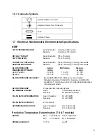
17
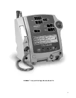
Front Panel Controls & Indicators (TS Model shown)
17
15
16
7
10
21
11
8
9
19
18
14
13
12
23
24
25
26
27
20
22
7
This push button switch controls the ON/
OFF state of the monitor. Push for power
ON and again for power OFF.
18
This 3 digit LED indicates SpO
?
Oxygen Saturation in %.
=
8
This green LED indicates the external
power and battery charging status of the
monitor.
19
PULSE BPM
DISPLAY
This 3-digit yellow LED display
shows pulse rate in Beats Per
Minute.
9
This yellow LED indicates operation and
charge status of the internal battery.
20
This yellow LED flashes, indicating
real-time pulse rate measurements
are derived from the SpO
2
signals.
10
ROTOR
CONTROL
This is used to highlight and select items in
the LCD menus. If the monitor is OFF,
pushing it will switch the monitor ON.
21
This 4 digit red LED Display
indicates the measured
Temperature.
11
LCD
This panel displays all alarms, user
interface messages & configuration
options.
22
°C °F DISPLAY
These indicate that Temperature is
being displayed in degrees Celsius
or Fahrenheit.
12
Press this key to begin or halt an NIBP
determination. The key also cancels STAT
mode.
23
TEMP. PROBE
CONNECTOR
Plug the predictive temperature
probe cable into this socket.
13
Press this key to begin or halt operation of
the STAT mode of NIBP monitoring.
24
SpO
2
SENSOR
CONNECTOR
Attach the SpO
2
sensor extension
cable to this socket.
=
14
This switch alternately mutes & enables
the audio alarm. When pressed once
(SILENCE ON) the switch lights indicating
audible alarms have been silenced.
25
CUFF
CONNECTOR
Insert the NIBP Cuff hose into this
connector.
15
SYSTOLIC
PRESSURE
This 3 digit red LED display indicates the
measured systolic B.P. in mmHg.
26
LIGHT SENSOR
Automatically measures ambient
light to set LED display intensity.
16
DIASTOLIC
PRESSURE
This 3 digit red LED display indicates the
measured diastolic B.P. in mmHg.
27
PRINTER DOOR
Open this door to gain access to the
paper.

