background image

*(.&

DIAC / DIFC / DSFC Digital Overcurrent Protection

19

0.1

2

3

4

5

5

6 7

1

2

3

4

5

5

6

10

2

3

4

5

5

6

100

0.01

2

3

4

4

5

6

0.1

2

3

4

4

5

6

1

2

3

4

4

5

6

10

2

3

4

4

5

6

100

2

DIAC, DIFC, & DSFC   

OVERCURRENT RELAYS 

IEEE Ext. Inv.

RESET

OPERATE

Extremely Inverse

.5

1

2

3

T

im

e

 D

ial 

S

e

tt

ings

4

5

6

7

8

9

9.9

Pow er M anagem ent

Frequency: 50/60 Hertz

0.1 - 3.18 (1 Ampere Relays)

General Electric CO., 205 Great Valley Parkway, Malvern, PA 19355

0358A1117

Multiples of Pickup Setting

Ti

m

e

 in

 Sec

o

nd

s

Time Dial Range: (0.5 - 9.9)

Current Range: 0.5 - 15.9 ( 5 Ampere Relays)

GES10036

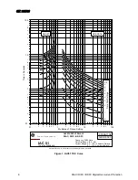
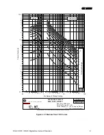
Figure 14: IEEE Extremely Inverse TOC Curves

Содержание DIAC

Страница 1: ...agement 215 Anderson Avenue Markham Ontario Canada L6E 1B3 Tel 905 294 6222 Fax 905 294 8512 Internet http www GEindustrial com pm Manufactured under an ISO9002 Registered system g GE Power Management Note All relays must be powered up at least once per year to avoid deterioration of electrolytic capacitors and subsequent relay failure ...

Страница 2: ......

Страница 3: ... HANDLING AND STORAGE 25 INSTALLATION 26 ENVIRONMENT 26 MOUNTING 26 SURGE GROUND DIAC AND DSFC 26 SURGE GROUND AND RFI IMMUNITY DIFC ONLY 26 ACCEPTANCE TESTS 33 VISUAL INSPECTION 33 MECHANICAL INSPECTION 33 ELECTRICAL TESTS 33 PERIODIC TESTS AND SERVICING 39 PERIODIC TESTS 39 SERVICING 39 SPECIFICATIONS 41 BURDENS 41 RATINGS 42 BURDENS 42 CONTACT RATINGS 42 ENVIRONMENTAL 42 INSULATION WITHSTAND TE...

Страница 4: ...ING 30 FIGURE 22 SURFACE MOUNTING DIFC 31 FIGURE 23 DSFC PANEL MOUNTING AND DRILLING 32 FIGURE 25 DIAC OR DSFC TEST SETUP FOR PICKUP AND OPERATING TIME VERIFICATION 37 FIGURE 26 DIFC TEST SETUP FOR INSTANTANEOUS UNIT 37 FIGURE 27 DIAC OR DSFC TEST SETUP FOR INSTANTANEOUS 38 FIGURE 28 9819647 8919648 DIAC FRONT AND REAR VIEWS 39 FIGURE 29 8919652 8919653 DIFC FRONT AND REAR VIEWS 40 FIGURE 30 89196...

Страница 5: ...on General purpose feeder protection 50 51 applications Self powered 16 Selectable curves Reset curve enable disable Low Burden Fully Retrofitable Functional separate TOC and IOC opera tions Wide settings range Drawout case construction When replacing unit and case see instruction manual INSTALLATION section for details 51 52 50 Main Bus To Load ...

Страница 6: ...igure 18 OR 19 Use of a separate ground relay provides more sensitive protection for ground faults The TOC reset characteristics can be set to emu late those of an induction disk or set for fast reset with no intentional delay Functions The TOC function operates on an RMS current calculated from the sampled values The IOC func tion operates on the sampled values and the algo rithm virtually elimin...

Страница 7: ...h of equation TD M t time Pickup TD M t time Reset 1 0 8 1 82 5 2 2 IEEE Inverse See Figure 12 for graph of equation TD M t time Pickup TD M t time Reset 0228 0 1 0103 1 97 02 0 2 IEEE Very Inverse See Figure 13 for graph of equation TD M t time Pickup TD M t time Reset 0982 0 1 922 3 1 32 4 2 2 IEEE Extremely Inverse See Figure 14 for graph of equation TD M t time Pickup TD M t time Reset 02434 0...

Страница 8: ...RCURRENT RELAYS IAC 51 RESET OPERATE 5 1 2 3 4 5 6 7 8 9 9 9 Time Dial Settings Inverse Standard Pow er M anagement Frequency 50 60 Hertz 0 1 3 18 1 Ampere Relays General Electric CO 205 Great Valley Parkway Malvern PA 19355 0358A1104 Multiples of Pickup Setting Time in Seconds Time Dial Range 0 5 9 9 Current Range 0 5 15 9 5 Ampere Relays GES10023 Figure 1 IAC51 TOC Curve ...

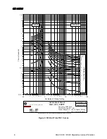
Страница 9: ...OVERCURRENT RELAYS IAC 53 RESET OPERATE 5 1 2 3 4 5 6 7 8 9 Time Dial Settings 9 9 Very Inverse Standard Pow er M anagement Frequency 50 60 Hertz 0 1 3 18 1 Ampere Relays General Electric CO 205 Great Valley Parkway Malvern PA 19355 0358A1105 Multiples of Pickup Setting Time in Seconds Time Dial Range 0 5 9 9 Current Range 0 5 15 9 5 Ampere Relays GES10024 Figure 2 IAC53 TOC Curves ...

Страница 10: ...CURRENT RELAYS 55 ST RESET OPERATE 5 1 2 3 4 5 6 7 8 9 9 9 Time Dial Settings Short Time Pow er M anagement Frequency 50 60 Hertz 0 1 3 18 1 Ampere Relays General Electric CO 205 Great Valley Parkway Malvern PA 19355 0358A1106 Multiples of Pickup Setting Time in Seconds Time Dial Range 0 5 9 9 Current Range 0 5 15 9 5 Ampere Relays GES10025 Figure 3 55 Short Time TOC Curves ...

Страница 11: ...RENT RELAYS 57 MT RESET OPERATE Time Dial Settings 5 1 2 3 4 5 6 7 8 9 9 9 Inverse Medium Pow er M anagement Frequency 50 60 Hertz 0 1 3 18 1 Ampere Relays General Electric CO 205 Great Valley Parkway Malvern PA 19355 0358A1107 Multiples of Pickup Setting Time in Seconds Time Dial Range 0 5 9 9 Current Range 0 5 15 9 5 Ampere Relays GES10026 Figure 4 57 Medium Time TOC Curves ...

Страница 12: ... OVERCURRENT RELAYS 66 LT RESET OPERATE Inverse Long 5 1 2 3 Time Dial Settings 4 5 6 7 8 9 9 9 Pow er M anagement Frequency 50 60 Hertz 0 1 3 18 1 Ampere Relays General Electric CO 205 Great Valley Parkway Malvern PA 19355 0358A1108 Multiples of Pickup Setting Time in Seconds Time Dial Range 0 5 9 9 Current Range 0 5 15 9 5 Ampere Relays GES10027 Figure 5 66 Long Time TOC Curves ...

Страница 13: ...RCURRENT RELAYS 75 ST RESET OPERATE Inverse Medium Short 5 1 2 3 Time Dial Settings 4 5 6 7 8 9 9 9 Pow er M anagement Frequency 50 60 Hertz 0 1 3 18 1 Ampere Relays General Electric CO 205 Great Valley Parkway Malvern PA 19355 0358A1109 Multiples of Pickup Setting Time in Seconds Time Dial Range 0 5 9 9 Current Range 0 5 15 9 5 Ampere Relays GES10028 Figure 6 75 Short Time TOC Curves ...

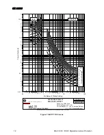
Страница 14: ...ERCURRENT RELAYS IAC 77 RESET OPERATE Extremely Inverse Standard 5 1 2 3 4 5 Time Dial Settings 6 7 9 9 9 8 Pow er M anagement Frequency 50 60 Hertz 0 1 3 18 1 Ampere Relays General Electric CO 205 Great Valley Parkway Malvern PA 19355 0358A1110 Multiples of Pickup Setting Time in Seconds Time Dial Range 0 5 9 9 Current Range 0 5 15 9 5 Ampere Relays GES10029 Figure 7 IAC77 TOC Curves ...

Страница 15: ...OVERCURRENT RELAYS 95 ST RESET OPERATE Inverse Short 5 1 2 3 4 5 Time Dial Settings 6 7 8 9 9 9 Pow er M anagement Frequency 50 60 Hertz 0 1 3 18 1 Ampere Relays General Electric CO 205 Great Valley Parkway Malvern PA 19355 0358A1111 Multiples of Pickup Setting Time in Seconds Time Dial Range 0 5 9 9 Current Range 0 5 15 9 5 Ampere Relays GES10030 Figure 8 95 Short Time TOC Curves ...

Страница 16: ...DSFC OVERCURRENT RELAYS IEC Inverse RESET OPERATE Time Dial Settings 3 2 1 5 4 5 6 7 8 9 9 9 Pow er M anagement Frequency 50 60 Hertz 0 1 3 18 1 Ampere Relays General Electric CO 205 Great Valley Parkway Malvern PA 19355 0358A1112 Multiples of Pickup Setting Time in Seconds Time Dial Range 0 5 9 9 Current Range 0 5 15 9 5 Ampere Relays GES10031 Figure 9 IEC Inverse TOC Curves ...

Страница 17: ... OVERCURRENT RELAYS IEC VERY INVERSE RESET OPERATE 5 1 2 3 4 5 6 9 9 7 8 9 Time Dial Settings Pow er M anagement Frequency 50 60 Hertz 0 1 3 18 1 Ampere Relays General Electric CO 205 Great Valley Parkway Malvern PA 19355 0358A1113 Multiples of Pickup Setting Time in Seconds Time Dial Range 0 5 9 9 Current Range 0 5 15 9 5 Ampere Relays GES10032 Figure 10 IEC Very Inverse TOC Curves ...

Страница 18: ...ENT RELAYS IEC Ext Inv RESET OPERATE Extremely Inverse 5 Time Dial Settings 9 9 9 8 7 6 5 4 3 2 1 Pow er M anagement Frequency 50 60 Hertz 0 1 3 18 1 Ampere Relays General Electric CO 205 Great Valley Parkway Malvern PA 19355 0358A1114 Multiples of Pickup Setting Time in Seconds Time Dial Range 0 5 9 9 Current Range 0 5 15 9 5 Ampere Relays GES10033 Figure 11 IEC Extremely Inverse TOC Curves ...

Страница 19: ...SFC OVERCURRENT RELAYS IEEE Inverse RESET OPERATE Time Dial Settings 5 1 2 3 4 5 6 7 8 9 9 9 Pow er M anagement Frequency 50 60 Hertz 0 1 3 18 1 Ampere Relays General Electric CO 205 Great Valley Parkway Malvern PA 19355 0358A1115 Multiples of Pickup Setting Time in Seconds Time Dial Range 0 5 9 9 Current Range 0 5 15 9 5 Ampere Relays GES10034 Figure 12 IEEE Inverse TOC Curves ...

Страница 20: ...URRENT RELAYS IEEE Very Inv RESET OPERATE Time Dial Settings 5 1 2 3 4 5 6 7 8 9 9 9 Very Inverse Pow er M anagement Frequency 50 60 Hertz 0 1 3 18 1 Ampere Relays General Electric CO 205 Great Valley Parkway Malvern PA 19355 0358A1116 Multiples of Pickup Setting Time in Seconds Time Dial Range 0 5 9 9 Current Range 0 5 15 9 5 Ampere Relays GES10035 Figure 13 IEEE Very Inverse TOC Curves ...

Страница 21: ...NT RELAYS IEEE Ext Inv RESET OPERATE Extremely Inverse 5 1 2 3 Time Dial Settings 4 5 6 7 8 9 9 9 Pow er M anagement Frequency 50 60 Hertz 0 1 3 18 1 Ampere Relays General Electric CO 205 Great Valley Parkway Malvern PA 19355 0358A1117 Multiples of Pickup Setting Time in Seconds Time Dial Range 0 5 9 9 Current Range 0 5 15 9 5 Ampere Relays GES10036 Figure 14 IEEE Extremely Inverse TOC Curves ...
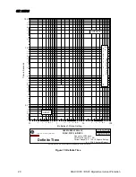
Страница 22: ...IFC DSFC OVERCURRENT RELAYS Definite Time RESET OPERATE Time Dial Settings 5 1 2 4 5 6 7 8 9 9 9 3 Pow er M anagement Frequency 50 60 Hertz 0 1 3 18 1 Ampere Relays General Electric CO 205 Great Valley Parkway Malvern PA 19355 0361A7502 Multiples of Pickup Setting Time in Seconds Time Dial Range 0 5 9 9 Current Range 0 5 15 9 5 Ampere Relays GES10038 Figure 15 Definite Time ...

Страница 23: ...DIFC DSFC OVERCURRENT RELAYS I2T RESET OPERATE 5 1 2 3 Time Dial Settings 4 5 6 7 8 9 9 9 Pow er M anagement Frequency 50 60 Hertz 0 1 3 18 1 Ampere Relays General Electric CO 205 Great Valley Parkway Malvern PA 19355 0358A1119 Multiples of Pickup Setting Time in Seconds Time Dial Range 0 5 9 9 Current Range 0 5 15 9 5 Ampere Relays GES10037 Figure 16 I 2 t Time Curve ...

Страница 24: ...0 1 times 250 and the maximum value is 2475 9 9 times 250 Multples of Pickup Setting 2 3 4 5 6 7 8 9 100 Time in Milliseconds 1 2 3 4 5 6 7 8 9 10 OVERCURRENT RELAYS DIAC DIFC DSFC Instantaneous 1 5 1 1 GES10039 Current Range 0 5 15 9 5 Ampere Relays 0361A7503 0 1 3 18 1 Ampere Relays Frequency 50 60 Hertz Power Management Figure 17 IOC Curve ...

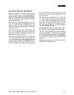
Страница 25: ...el and 0 1 to 3 18 amps in 0 02 amp increments for the 1 amp model a setting of 0 disables the TOC element The time dial can be set from 0 5 to 9 9 in 0 1 increments on both the 5 amp model and the 1 amp model The only exception is for the Definite Time and I2T curves where 0 1 is the minimum value The IOC function is settable from 1 to 159 amps in 1 amp increments for the 5 amp model and 0 2 to 3...

Страница 26: ... position The TOC pickup current is set directly in Amps with two rotary switches An arrow is used to in dicate setting position Setting the TOC or the IOC pickup current between but not including 0 and a value less than minimum 0 5 5 amp or 0 1 1 amp will result in the relay defaulting to its minimum setting Setting the TOC or IOC pickup current to 0 will disable their respective ele ments Althou...

Страница 27: ...o have the positive battery ter minal connected to Stud 1 for the TOC and IOC trip circuit and the negative to Stud 2 TOC and Stud 3 IOC NOTE Both trip circuits are suitable for use with Cap Trip devices Cover Installation DIAC and DSFC NOTE When replacing the cover on the DIAC and DSFC relays the reset wire should be locked behind the nameplate by a slight left to right motion to place the reset ...

Страница 28: ...tion is available for the DIFC relay Surge Ground DIAC and DSFC The relay should be grounded to the station ground mat with a 12 AWG braided ground lead connected to terminal 4 If the relay is to be retrofitted in a panel terminal 4 should be removed from the new case and installed into the old case For the surge protection to function properly the relay must be grounded Surge Ground and RFI Immun...

Страница 29: ... DIAC DIFC DSFC Digital Overcurrent Protection 27 Figure 18 DIAC and DSFC External Internal Connections ...

Страница 30: ... 28 DIAC DIFC DSFC Digital Overcurrent Protection Figure 19 DIFC External Internal Connections ...

Страница 31: ...168MM 29MM 19MM 157MM 9 125 232MM 4 406 112MM 3 906 99MM 76MM 1 125 144MM BACK VIEW C L L C L C 15MM 19MM MTG MTG SEMI FLUSH SURFACE 2 5 16 18 STUDS FOR SURFACE MTG 10 32 STUDS 8 375 212MM 76MM TYPICAL DIM INCHES MM VIEW SHOWING ASSEMBLY OF HARDWARE FOR SURFACE MTG ON STEEL PANELS PANEL DRILLING FOR SEMI FLUSH MOUNTING FRONT VIEW 5 16 18 STUD PANEL DRILLING FOR SURFACE MOUNTING FRONT VIEW 1 4 DRIL...

Страница 32: ...G FOR 2 375 4 750 469 156 625 TYP PANEL DRILLING REFER TO RELAY FOR QUANTITY OF HOLES 750 625 NUT HDW 0257A8549 G2 VIEW C REMOVE KNOCKOUT 8 36 SCREW WASHER MOUNTING SURFACE LKWASH SURFACE MOUNTING WASHER 8 36 VIEW B HDW 0257A8549 G2 NUT 2 219 HLS SPACER LOCK WASHER SCREW REMOVE KNOCKOUT OVERSIZE WASHERS 2 500 8 344 188 5MM THK MAX PANEL F OR 312 HLS 7 376 187MM 94MM 154MM PANEL DRILLING 5 562 141M...

Страница 33: ...OUNTING FOR 2 375 4 750 469 156 625 TYP PANEL DRILLING REFER TO RELAY FOR QUANTITY OF HOLES 750 625 NUT HDW 0257A8549 G2 VIEW C REMOVE KNOCKOUT 8 36 SCREW WASHER MOUNTING SURFACE LKWASH SURFACE MOUNTING WASHER 8 36 VIEW B HDW 0257A8549 G2 NUT 2 219 HLS SPACER LOCK WASHER SCREW REMOVE KNOCKOUT OVERSIZE WASHERS 2 500 8 344 188 5MM THK MAX PANEL F OR 312 HLS 7 376 187MM 94MM 154MM PANEL DRILLING 5 56...

Страница 34: ...19MM 157MM 7 177MM 3 343 84MM 2 844 72MM 76MM 1 125 144MM BACK VIEW C L L C L C 15MM 19MM MTG MTG SEMI FLUSH SURFACE 2 5 16 18 STUDS FOR SURFACE MTG 10 32 STUDS 5 625 142MM 76MM TYPICAL DIM INCHES MM VIEW SHOWING ASSEMBLY OF HARDWARE FOR SURFACE MTG ON STEEL PANELS PANEL DRILLING FOR SEMI FLUSH MOUNTING FOR SEMI FLUSH MOUNTING FRONT VIEW 5 16 18 STUD PANEL DRILLING FOR SURFACE MOUNTING FRONT VIEW ...

Страница 35: ...e the XCA test plug for a V or S case use the XLA series test plug refer to the GE Power Management Product Catalog Although the test plugs provide greater flexibility it re quires C T shorting jumpers and exercise of greater care since connections are made to both the relay and the external circuitry INVERSE TIME UNIT Pickup Verification Connect the relay as indicated in Figure 24 or 25 In order ...

Страница 36: ...47 2 17 28 19 1 10 78 11 9 75 ST 0 748 0 827 0 3113 0 344 0 244 0 2707 IAC 77 6 49 7 17 0 859 0 954 0 266 0 296 95 ST 0 895 0 994 0 356 0 396 0 276 0 303 IEEE Inverse 3 59 3 99 1 59 1 76 1 12 1 25 IEEE Very Inverse 6 51 7 24 1 21 1 34 0 64 0 71 IEEE Ext Inverse 8 76 9 73 1 18 1 32 0 374 0 412 IEC Inverse 4 73 5 26 2 0 2 22 1 39 1 54 IEC Very Inverse 6 31 7 014 1 56 1 73 0 69 0 768 IEC Ext Inverse ...

Страница 37: ... 0 23 0 10 0 12 0 058 0 064 57 MT 17 3 19 3 12 2 13 65 5 27 5 86 1 783 1 98 66 LT 33 9 37 7 24 1 26 7 10 3 11 4 3 46 3 848 75 ST 0 577 0 641 0 424 0 471 0 2 0 221 0 09 0 1 IAC77 1 81 2 013 1 2 1 33 0 545 0 605 0 228 0 253 95 ST 0 69 0 767 0 49 0 544 0 23 0 252 0 102 0 11 IEC Inverse 3 94 4 37 2 79 3 1 1 21 1 34 0 431 0 478 IEC Very Inverse 3 06 3 402 2 17 2 415 0 95 1 05 0 332 0 369 IEC Ext Invers...

Страница 38: ...Connect the relay as shown in Figure 26 or 27 Set the instantaneous unit pickup to 2 amps 5 amp rated relay or 0 4 amps 1 amp rated relay with a zero IOC delay setting Apply 6 amps 5 amp rated relay or 1 2 amps 1 amp rated relay and measure the operating time The operating time should be between 32 ms and 46 ms This time is subject to dependent on the multiple of pickup current and the fault incid...

Страница 39: ...ve 36 300 V DC Power Supply Current Limited to 200 mA Positive Figure 25 DIAC or DSFC Test Setup for Pickup and Operating Time Verification Target and Seal In AUX TOC Contact T7 T8 T2 I in T5 T6 Single Phase Current Source Start Stop TIMER Negative 36 300 V DC Power Supply Current Limited to 200 mA Positive Figure 26 DIFC Test Setup for Instantaneous Unit ...

Страница 40: ...rent Protection Target and Seal In AUX TOC Contact T7 T8 T2 I in T5 T6 Single Phase Current Source Start Stop TIMER Negative 36 300 V DC Power Supply Current Limited to 200 mA Positive Figure 27 DIAC or DSFC Test Setup for Instantaneous ...

Страница 41: ... inspecting the contacts for corrosion Servicing If the relay fails to perform as specified in this instruction manual consult the factory or call your local GE sales office Before returning the relay consult with the factory s technical support It is not recommended that the relay be serviced to the component level This requires substantial investment in repair test equipment and in technical exp...

Страница 42: ... 40 DIAC DIFC DSFC Digital Overcurrent Protection Figure 29 8919652 8919653 DIFC Front and Rear Views Figure 30 8919632 8919661 DSFC Front and Rear Views ...

Страница 43: ...en Settings Burden Minimum Setting Burden in ohms Z at multiples of minimum pickup Unit Range Hz R jX Z 3 10 20 100 1 A 0 1 31 8 60 28 8 29 2 41 3 45 9 36 2 32 1 24 0 768 5 A 0 5 15 9 60 1 28 1 15 1 74 42 0 394 0 094 0 052 0 034 4 5 5 6 7 8 1 2 3 4 5 5 6 7 10 2 3 4 5 5 6 100 3 4 1 2 3 3 4 10 2 3 3 4 100 2 DIAC DIFC DSFC OVERCURRENT RELAYS Burden 0 1 2 3 4 5 5 6 7 8 1 2 3 4 5 5 6 7 10 2 5AMP Model ...

Страница 44: ...or settings Contact Ratings Output Contacts Voltage Cont Make and carry 1 sec Break Max load DC Resistive 125V 250V 10A 30A 0 5A 0 3A 60W DC Inductive L R 40ms 125V 250V 370V 10A 30A 0 25A 0 15A 0 05A 50VA NOTE Suitable for Cap Trip devices Environmental Ambient Temperature Storage 40 to 85 C Operation 40 to 70 C Humidity Up to 95 without condensing Insulation Withstand Tests Impulse Voltage 5 kV ...

Страница 45: ... uses a seal in unit as its tripping ele ment The trip contact remains closed until the trip circuit drops below 0 19 A A breaker contact 52a can be provided in series with the trip cir cuit to reset the target once the breaker tripped on fault TOC IOC Trip Coil DC Supply DC Supply Breaker Contact 52a T3 T1 T2 Figure 32 IOC TOC UNIT ...

Страница 46: ... 3RZHU 0DQDJHPHQW 215 Anderson Avenue Markham Ontario Canada L6E 1B3 Tel 905 294 6222 Fax 905 201 2098 www GEindustrial com pm ...

Отзывы: