


*(.&
DIAC / DIFC / DSFC Digital Overcurrent Protection
33
ACCEPTANCE TESTS
Immediately upon receipt of the relay, an
inspection and acceptance test should be made
to make sure that no damage has been
sustained in shipment, and that the relay
calibrations have not been disturbed.
Visual Inspection
Check the nameplate stamping to make sure
that the model number and rating of the relay
agree with the requisition. Remove the relay
from its case and check that there are no broken
or cracked molded parts or other signs of
physical damage, and that all screws are tight.
Mechanical Inspection
1.
The target and seal-in unit, pull and lift
the TOC lever to test the target, repeat
the test for the IOC target. The Target
flag should remain when the lever is re-
leased. Reset the target by pushing the
reset bar.
2.
Make sure that the fingers and shorting
bars agree with the internal connections
diagram.
CAUTION: Every circuit in the drawout case
has an auxiliary brush. It is especially impor-
tant on current circuits and other circuits
with shorting bars that auxiliary brush be
bent high enough to engage the connection
plug or test plug before the main brushes do.
This will prevent CT (current Transformer)
secondary circuits from being opened.
Electrical Tests
DRAWOUT RELAYS, GENERAL
Since all drawout relays in service operate in
their cases, it is recommended that they be
tested in their cases or an equivalent case. A
relay may be tested without removing it from the
panel by using the appropriate test plug. For a C
case, use the XCA test plug; for a V or S case,
use the XLA series test plug (refer to the GE
Power Management Product Catalog). Although
the test plugs provide greater flexibility, it re-
quires C.T. shorting jumpers and exercise of
greater care since connections are made to both
the relay and the external circuitry.
INVERSE TIME UNIT
Pickup Verification
•
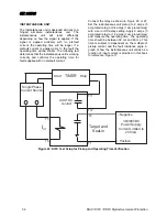
Connect the relay as indicated in Figure 24
or 25. In order to apply current to the relay,
use a 50/60 Hz voltage source, with a vari-
able resistor in series, or an electronic cur-
rent source.
•
Set the relay at the desired pickup TOC and
disable the instantaneous unit by setting the
instantaneous current setting to zero (0).
Apply current to the relay and verify that the
Pickup LED on the front of the relay lights be-
tween 98% and 102% of the pickup TOC setting.
If the relay is set to blink between power up and
pickup, look for the LED to be on most or all of
the time to indicate pickup.
Reduce the current applied, verifying that at a
value between 95% and 100% of the pickup
TOC, the relay Pickup LED turns off or blinks if
set to blink.
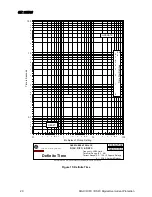
Verification of Operating Time
Because the Digital self powered series of relays
has many different curve characteristics, the
basic test instruction will be given and the data
for each of the curves can be found in Table 1.
With the relay still connected as indicated in
Figure 24 or 25, set the time overcurrent unit to
minimum pickup and set the corresponding time
dial to 5. Successively apply currents of 2, 5, and
10 times pickup TOC, verifying that the operating
times are within the margins indicated in Table 1.
NOTE: Before attempting to reset the trip
target, ensure the DC supply is removed or
turned off from the trip circuit setup