October 2007
2-14
Installation
Flow Rate
It is important to have adequate flow through the sensor. Too little
flow can slow the response (particularly at very low frost points). Too
much flow can cause instability of the control system at high dew
points and can reduce the depression capability of the thermoelectric
cooler at very low dew points. Too much flow also accelerates the
rate of system contamination. A flow rate of 2 to 2.5 ft
3
/h (
∼
1 liter/
min) is ideal for most applications.
Sensor Installation
This section provides installation details for the GE Sensing line of
chilled-mirror humidity sensors.
Model 1111H Sensor
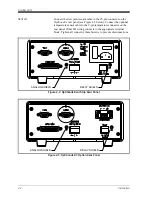
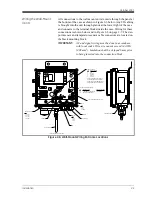
The Model 1111H is an open-type sensor (see Figure 2-12 below)
with 45°C depression capability at 25°C @ 1 ATM. It can be threaded
into standard pipe fittings or mounted in a type 0111D pressure boss,
which encloses it and adapts it for ¼-inch compression fittings. When
installing the sensor in the pressure boss, remove the black aluminum
sensor cover. A second version, the 1111H-GE, extends 9 in. and
includes a duct-mounted flange and a removable PTFE filter.
For maximum thermal conductivity, the base of the Model 0111D
pressure boss should be coated with heat-conducting grease. When so
installed on a surface suitable for dissipating heat, the sensor will
achieve its maximum rated depression. See the
Chilled Mirror Sensor
Comparison Chart
in Appendix D.
Figure 2-12: Model 1111H Sensor for Duct Mounting
Содержание 1111H
Страница 1: ...GE Sensing OptiSonde General Eastern Chilled Mirror Hygrometer User s Manual ...
Страница 9: ...Chapter 1 ...
Страница 10: ...Features and Capabilities Introduction 1 1 Electronics Enclosure 1 2 The System 1 3 Sensors 1 4 ...
Страница 15: ...Chapter 2 ...
Страница 33: ...Chapter 3 ...
Страница 43: ...Chapter 4 ...
Страница 44: ...Programming the OptiSonde Introduction 4 1 Programming Technique 4 2 Programmable Functions 4 3 ...
Страница 57: ...Chapter 5 ...
Страница 68: ...Appendix A ...
Страница 73: ...Appendix B ...
Страница 74: ...Humidity Equations and Conversion Chart Introduction B 1 Vapor Pressure B 1 Humidity B 2 ...
Страница 77: ...Humidity Equations and Conversion Chart B 3 October 2007 Figure B 1 Graphical Humidity Conversion Chart ...
Страница 78: ...Appendix C ...
Страница 79: ...Configuring the Serial Interface Wiring to a Personal Computer C 1 ...
Страница 82: ...Appendix D ...
Страница 83: ...Chilled Mirror Sensors Introduction D 1 Depression D 1 Measurement Range D 2 Comparing OptiSonde Sensors D 3 ...
Страница 87: ...Appendix E ...
Страница 88: ...Theory of Operation and Glossary Theory of Operation E 1 The PACER Cycle E 4 Glossary E 5 ...


