Main -> Local -> Optics -> Info:
The Info Menu shows the wavelength (normally 1310nM), maximum distance
(normally 15km) and optic transceiver vendor name (Infineon) for the selected
optic transceiver. Use the "+" button to select the next transceiver. Use the "-" button
to select the previous transceiver.
Main -> Local -> Video:
Video Input and Video Output mapping, monitoring, and tests can be accessed from the
sub-menus.
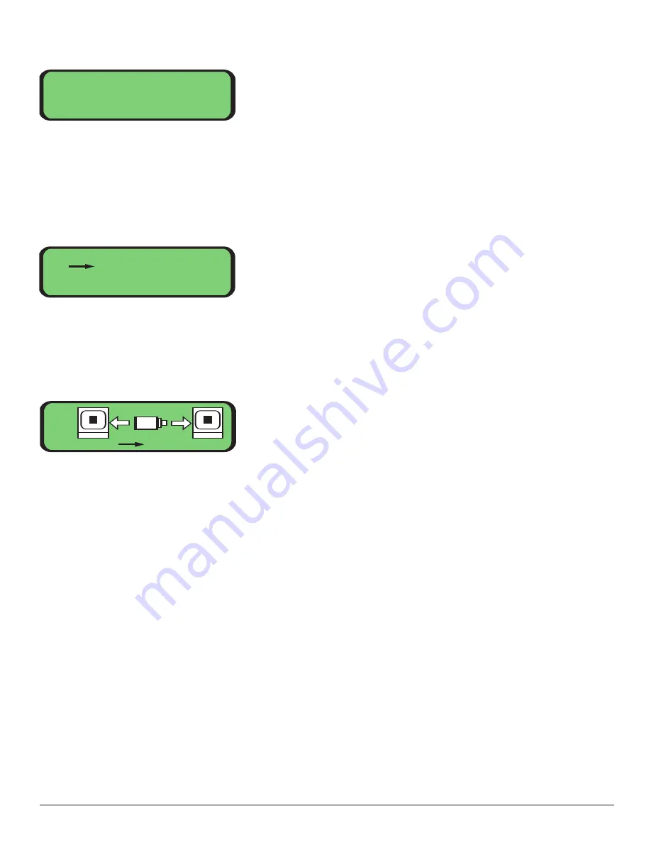
Main -> Local -> Video -> Input Mapping:
This screen allows you to assign a video input channel to a video output channel over a
selected fiber port. The camera icon in the middle of the screen indicates the presence
of a video signal for the selected channel. If the camera has an X through it, video is not
present on this channel. If the camera does not have an X through it, then video is
present. The number under the camera icon indicates the currently selected input
channel. The numbers under the monitor icons to the left and/or right of the camera
represent the output channel numbers. The arrows to the left and/or right of the
camera (labeled A and B, respectively) indicate over which fibers this mapping is
enabled. If the selected input channel is mapped to the output channel then a black
square is shown in the middle of the monitor icon and the arrow is displayed. If a
mapping does not exist for this input and output channel pair, then the monitor icon
is blank and the arrow is not shown.
Use the "left" and "right" button to move the cursor at the bottom of the screen. Use "+"
and "-" to increment and decrement the channel numbers. Incrementing the input
channel automatically increments both output channels. Press "enter" while the cursor is
at an output channel to enable a mapping. Move the cursor to "Exit" and press enter to
leave this screen. All channel mapping are saved when you leave this menu.
Video Menu
1. Input Mapping
2. Output Mapping
3. Test Select
Optic Info: ABCD
Wavelength: 1310 nM
Max Distance: 15 km
Vendor: Infineon
Video:
Exit
A
B
1
1
1
31


