


GE Multilin
C60 Breaker Protection System
B-29
APPENDIX B
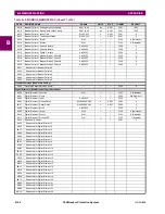
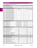
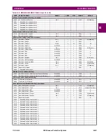
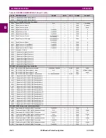
B.4 MEMORY MAPPING
B
5F8A
Setting Group Events
0 to 1
---
1
F102
0 (Disabled)
Setting Groups (Read Only)
5F8B
Current Setting Group
0 to 5
---
1
F001
0
Setting Group Names (Read/Write Setting)
5F8C
Setting Group 1 Name
---
---
---
F203
(none)
5F94
Setting Group 2 Name
---
---
---
F203
(none)
5F9C
Setting Group 3 Name
---
---
---
F203
(none)
5FA4
Setting Group 4 Name
---
---
---
F203
(none)
5FAC
Setting Group 5 Name
---
---
---
F203
(none)
5FB4
Setting Group 6 Name
---
---
---
F203
(none)
Sensitive Directional Power (Read/Write Grouped Setting) (2 modules)
66A0
Sensitive Directional Power 1 Function
0 to 1
---
1
F102
0 (Disabled)
66A1
Sensitive Directional Power 1 Signal Source
0 to 5
---
1
F167
0 (SRC 1)
66A2
Sensitive Directional Power 1 RCA
0 to 359
degrees
1
F001
0
66A3
Sensitive Directional Power 1 Calibration
0 to 0.95
degrees
0.05
F001
0
66A4
Sensitive Directional Power 1 STG1 SMIN
-1.2 to 1.2
pu
0.001
F002
100
66A5
Sensitive Directional Power 1 STG1 Delay
0 to 600
s
0.01
F001
50
66A6
Sensitive Directional Power 1 STG2 SMIN
-1.2 to 1.2
pu
0.001
F002
100
66A7
Sensitive Directional Power 1 STG2 Delay
0 to 600
s
0.01
F001
2000
66A8
Sensitive Directional Power 1 Block
---
---
---
F001
0
66A9
Sensitive Directional Power 1 Target
0 to 2
---
1
F109
0 (Self-reset)
66AA
Sensitive Directional Power 1 Events
0 to 1
---
1
F102
0 (Disabled)
66AB
Reserved (5 items)
0 to 65535
---
1
F001
0
66B0
...Repeated for Sensitive Directional Power 2
Autoreclose 1P 3P (Read/Write Setting)
6890
Autoreclose Mode
0 to 3
---
1
F080
0 (1 & 3 Pole)
6891
Autoreclose Maximum Number of Shots
1 to 4
---
1
F001
2
6892
Autoreclose Block Breaker 1
0 to 65535
---
1
F300
0
6893
Autoreclose Close Time Breaker 1
0 to 655.35
s
0.01
F001
10
6894
Autoreclose Breaker Manual Close
0 to 65535
---
1
F300
0
6895
Autoreclose Function
0 to 1
---
1
F102
0 (Disabled)
6896
Autoreclose Block Time Manual Close
0 to 655.35
s
0.01
F001
1000
6897
Autoreclose 1P Initiate
0 to 65535
---
1
F300
0
6898
Autoreclose 3P Initiate
0 to 65535
---
1
F300
0
6899
Autoreclose 3P TD Initiate
0 to 65535
---
1
F300
0
689A
Autoreclose Multi-Phase Fault
0 to 65535
---
1
F300
0
689B
Autoreclose Breaker 1 Pole Open
0 to 65535
---
1
F300
0
689C
Autoreclose Breaker 3 Pole Open
0 to 65535
---
1
F300
0
689D
Autoreclose 3-Pole Dead Time 1
0 to 655.35
s
0.01
F001
50
689E
Autoreclose 3-Pole Dead Time 2
0 to 655.35
s
0.01
F001
120
689F
Autoreclose Extend Dead T1
0 to 65535
---
1
F300
0
68A0
Autoreclose Dead T1 Extension
0 to 655.35
s
0.01
F001
50
68A1
Autoreclose Reset
0 to 65535
---
1
F300
0
68A2
Autoreclose Reset Time
0 to 655.35
s
0.01
F001
6000
68A3
Autoreclose Breaker Closed
0 to 65535
---
1
F300
0
68A4
Autoreclose Block
0 to 65535
---
1
F300
0
68A5
Autoreclose Pause
0 to 65535
---
1
F300
0
68A6
Autoreclose Incomplete Sequence Time
0 to 655.35
s
0.01
F001
500
68A7
Autoreclose Block Breaker 2
0 to 65535
---
1
F300
0
68A8
Autoreclose Close Time Breaker 2
0 to 655.35
s
0.01
F001
10
68A9
Autoreclose Transfer 1 to 2
0 to 1
---
1
F126
0 (No)
68AA
Autoreclose Transfer 2 to 1
0 to 1
---
1
F126
0 (No)
68AB
Autoreclose Breaker 1 Fail Option
0 to 1
---
1
F081
0 (Continue)
68AC
Autoreclose Breaker 2 Fail Option
0 to 1
---
1
F081
0 (Continue)
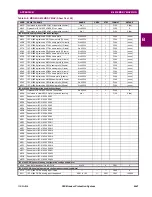
Table B–9: MODBUS MEMORY MAP (Sheet 22 of 50)
ADDR
REGISTER NAME
RANGE
UNITS
STEP
FORMAT
DEFAULT
Содержание C60 UR series
Страница 2: ......
Страница 4: ......
Страница 11: ...GE Multilin C60 Breaker Protection System xi TABLE OF CONTENTS INDEX...
Страница 12: ...xii C60 Breaker Protection System GE Multilin TABLE OF CONTENTS...
Страница 32: ...1 20 C60 Breaker Protection System GE Multilin 1 5 USING THE RELAY 1 GETTING STARTED 1...
Страница 50: ...2 18 C60 Breaker Protection System GE Multilin 2 2 SPECIFICATIONS 2 PRODUCT DESCRIPTION 2...
Страница 98: ...3 48 C60 Breaker Protection System GE Multilin 3 4 MANAGED ETHERNET SWITCH MODULES 3 HARDWARE 3...
Страница 128: ...4 30 C60 Breaker Protection System GE Multilin 4 3 FACEPLATE INTERFACE 4 HUMAN INTERFACES 4...
Страница 390: ...8 18 C60 Breaker Protection System GE Multilin 8 3 ENERVISTA SECURITY MANAGEMENT SYSTEM 8 SECURITY 8...
Страница 394: ...9 4 C60 Breaker Protection System GE Multilin 9 1 FAULT LOCATOR 9 THEORY OF OPERATION 9...
Страница 516: ...D 10 C60 Breaker Protection System GE Multilin D 1 OVERVIEW APPENDIXD D...
Страница 528: ...E 12 C60 Breaker Protection System GE Multilin E 2 DNP POINT LISTS APPENDIXE E...


