DISPLAY AND KEYBOARD
3-5
Number
Name
Description
RESET IMPOSSIBLE
ALARM PRESENT
8
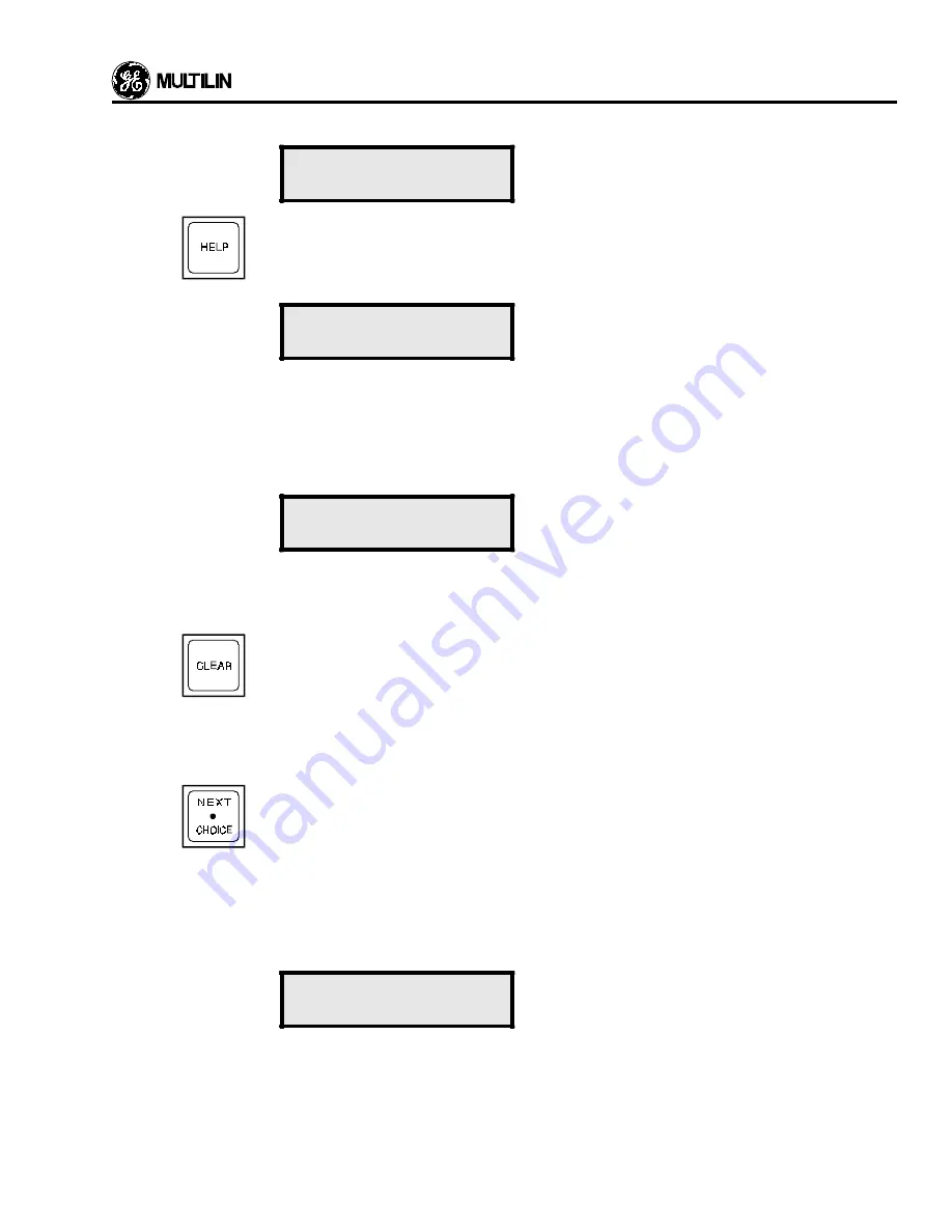
The HELP key provides the user with information on the function and use of each key on the keypad.
It also provides information about the currently displayed actual values or setpoints message. If
information is needed on the use of any of the keys on the keypad, use the LINE UP or PAGE key
to display the first line of any page. Then press the HELP key and the following message will appear:
PRESS ANY KEY
OR HELP
The user should then press the key for which instruction is required, for example, the PAGE key. If
information is needed on the previously displayed actual values or setpoints message, press HELP
again.
The HELP key can also be pressed on any line of either setpoints or actual values to get information
on that particular setpoint or actual value. If this is done the following message will appear:
PRESS LINE DOWN
TO SCROLL
Pressing LINE DOWN will allow the help message to be viewed. Pressing CLEAR will return the
display to the line where help was requested. Continue pressing LINE DOWN to display the entire
help message.
9
The CLEAR key performs two functions.
1. In the setpoints mode, pressing this key will return an altered unstored setpoint to its original
value. This might be used if you keyed in an incorrect value and had not yet stored it. Once a
value is stored it cannot be altered using the CLEAR key.
2. In the Help mode the key allows the user to return to the previous display mode as described in
number 8.
10
This key, which also functions as the decimal point key is used to view a list of items which cannot
be shown on the display at once. Pressing the NEXT CHOICE key once will cause the first item from
the list to be displayed, pressing it again will display the second item, and so on. When the last item
is reached pressing the key will cause the first item to be displayed again. The entire list can thus
be viewed as many times as needed. The following example shows the use of the NEXT CHOICE
key.
For example, in Setpoints Mode page 3, the ground protection curve is chosen from a list of 5
curves. When this line is first read it will display the curve in use, the Extremely Inverse curve being
shown below.
GND O/C CURVE
SHAPE: EXTREM INV
To advise the user that the NEXT CHOICE key may be used to display other curves, the bottom line
of this display will change for two seconds, and the following display will be seen:
Содержание 565
Страница 6: ...INSTALLATION 2 2 Figure 2 1 Mounting Details ...
Страница 7: ...INSTALLATION 2 3 Figure 2 2 Mounting Arrangement with Relay Collar ...
Страница 12: ...INSTALLATION 2 8 Figure 2 5 565 Relay Typical Wiring ...
Страница 13: ...INSTALLATION 2 9 Figure 2 6 Voltage Sensing Wire ...
Страница 14: ...INSTALLATION 2 10 Figure 2 7A 565 with MTM CT and Open Delta VT Typical Wiring ...
Страница 15: ...INSTALLATION 2 11 Figure 2 7B 565 with MTM CT and Wye VT Typical Wiring ...
Страница 16: ...INSTALLATION 2 12 Figure 2 8A Open Delta VT and CT MTM Typical Wiring ...
Страница 17: ...INSTALLATION 2 13 Figure 2 8B Wye VT and CT MTM Typical Wiring ...
Страница 18: ...INSTALLATION 2 14 Figure 2 9 MTM Mounting Dimensions ...
Страница 19: ...INSTALLATION 2 15 Figure 2 10 565 Rear Panel Layout ...
Страница 20: ......
Страница 23: ...DISPLAY AND KEYBOARD 3 3 Figure 4 1 565 Relay Front Panel ...
Страница 28: ......
Страница 132: ......
Страница 142: ...CURVE INFORMATION ANDTABLES 7 10 Figure 7 9 IEC A Curves ...
Страница 143: ...CURVE INFORMATION ANDTABLES 7 11 Figure 7 10 IEC B Curves ...
Страница 144: ...CURVE INFORMATION ANDTABLES 7 12 Figure 7 11 IEC C Curves ...
Страница 176: ...RELAYTESTING 8 2 Figure 8 1 Secondary Injection Test Setup ...
Страница 180: ......
Страница 184: ......
Страница 192: ...APPENDIX C C 2 Figure C1 System Controller Block Diagram 1 2 ...
Страница 193: ...APPENDIX C C 3 Figure C2 System Controller Block Diagram 2 2 ...
Страница 194: ......
Страница 198: ......


