Alarm Jumper
Rack cards are supplied with an alarm function that activates if
the optical signal input to the receiver fails. The alarm is
always indicated on the front panel of the card by a red
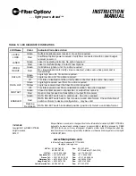
LEVEL/LOSS
TM
LED. The alarm may also be output to the
rack power supply, where a sonalert (audible alarm) and alarm
output contact closure may be activated.
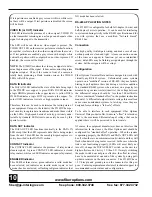
The alarm is set to ON (ACTIVE) at the factory. If the alarm
output is not desired, move jumper JP1 on the receiver or JP4
on the transmitter to the OFF position. Refer to Figures 4 and
5.
NOTE:
Setting alarm to OFF (inactive) does not affect the
operation of the LEVEL/LOSS
TM
LED. Loss of optical signal
will always be indicated by a red LEVEL/LOSS
TM
LED.
www.fiberoptions.com
free phone: 800.342.3748
free fax: 877.342.3732
4
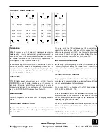
FIGURE 5: RACK-MOUNT TRANSMITTER - SWITCH AND JUMPER LOCATIONS
VIDEO CARD
DATA CARD
DATA SELECT
SWITCH SW1
8
1
DATA CONNECTOR
RELAY/CONTACT 1/2 CONNECTOR
RELAY/CONTACT 3/4 CONNECTOR
VIDEO IN 1
VIDEO IN 2
VIDEO IN 3
VIDEO IN 4
OPTICAL
CONNECTOR
JP1
NTSC
PAL
DISABLE
JP4
OFF
2
ON ALARM


