


GENERAL
This manual is a guide to the installation and operation of the
S734DV and S7734DV series fiber optic video and multi-
protocol data (MPD) transmission system. Please read the
entire manual before installing the equipment.
NOTE:
The series numbers S734DV, S734DVT and
S734DVR are used to describe all models of transmitters and
receivers unless noted otherwise.
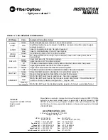
The Series S734DV and S7734DV video and MPD transmis-
sion system offers simultaneous transmission of four channels
of digital video and plus duplex digital control data. It also
offers four one-way channels of contact closure/relay trans-
mission.
The S734DV system operates over one multimode fiber while
the S7734DV uses one single-mode fiber.
A complete system consists of an S734DVT transmitter and an
S734DVR receiver. Units are designed for standalone opera-
tion or for installation in Fiber Options’ 515R1 or 517R1 Card
Cages or 502R standalone enclosures.
Unpacking the Unit
In the event that anything is missing from the following list,
contact your authorized Fiber Options dealer or representative.
S734DVT Transmitter or S734DVR Receiver
(S7734DVT Transmitter or S7734DVR Receiver)
Instruction manual
Save the original packing materials in case it becomes neces-
sary to return the unit.
INSTALLATION
Installation Considerations
This fiber-optic link is supplied as a standalone module or as a
rack card. Units should be installed in dry locations protected
from extremes of temperature and humidity.
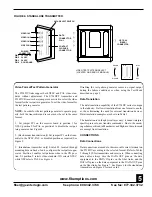
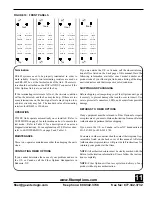
Standalone Modules
1. Determine where the module will be installed, and ensure
that there is adequate space at both ends for making the various
cable connections.
2. Standalone modules feature a wall-mounting plate which is
attached to suitable flat surfaces with six No. 6 (3-mm or
3.5-mm) screws. Once the plate is securely attached to a flat
surface, the S734DV is mounted on the plate and can be easily
removed. Refer to Figure 1 for details.
3. An additional, optional bracket is also provided for more
secure mounting. The type of screws must be suitable for the
surface where a module will be mounted. Refer to Figure 2.
Fiber Options
80 Orville Drive, Bohemia NY 11716-2533
US Tel
: 631-567-8320 or 800-342-3748
Fax
: 877-FiberFax (877-342-3732 toll free) or 631-567-8322
For international offices, see the back cover.
www.fiberoptions.com
GE Interlogix
Fiber Options
MODELS S
S734DV &
& S
S7734DV
FOUR-C
CHANNEL V
VIDEO W
WITH M
MULTI-P
PROTOCOL D
DATA
g
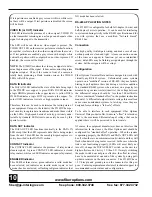
SYSTEM DIAGRAM
one
optical fiber
S734DVT
S734DVR
Video In 1-4
4 Contact Closure
Multi-protocol Data
Video Out 1-4
4 Contact Closure
Multi-protocol Data
INSTRUCTION
MANUAL


