2–2
EPM 4
5
00 SUB METER – INSTRUCTION MANUAL
WIRING
CHAPTER 2: INSTALLATION
2.2
Wiring
2.2.1
Overview of Meter Wiring
Although this document treats the installation and certification stages separately, this
does not imply that the recommended procedure is to install the entire system at once and
then proceed to certification.
The recommended procedure is to install and certify the system in stages. By doing this,
systematic error can be corrected before it propagates through the entire installation. To
follow the recommended procedure, divide the job up into manageable stages and install
and certify at each stage before proceeding to the installation of the next stage.
For the purposes of this discussion, the colors black, red and blue have been chosen to
distinguish among the three phases of a three-phase network. White is the designated
color of neutral and green is the color of earth ground. Please substitute the correct color
according to local electrical code. For a two-phase installation, ignore the third phase (the
blue phase in the following description).
Failure to follow the proper procedures and reference the correct wiring diagram can
result in damage to the equipment and/or physical harm.
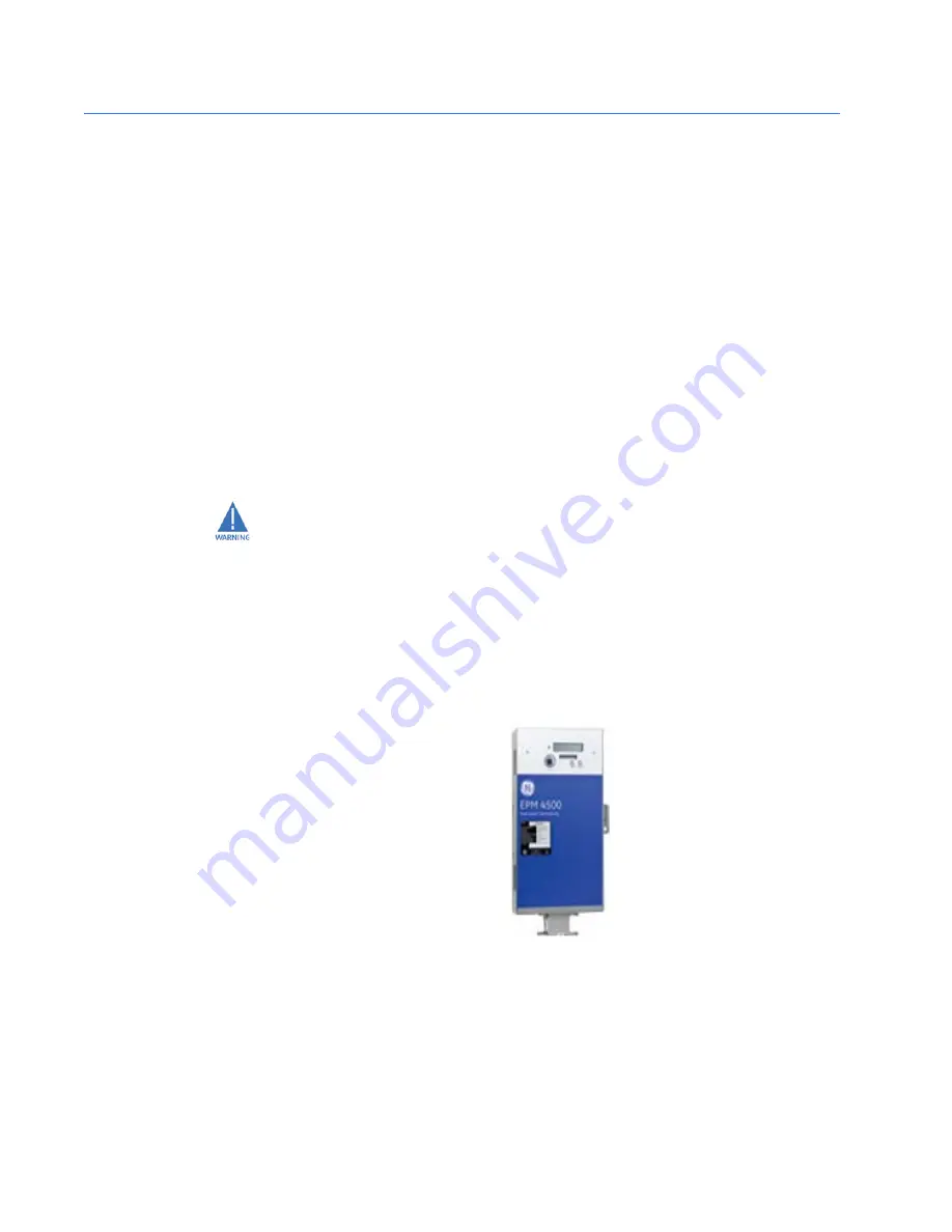
FIGURE 2–1: Vertical Mounting Option
2.2.2
Wiring Overview
Review the following wiring types and select the one that matches your installation
requirements and part number using the following table.
709714A1.CDR
Содержание EPM 4500
Страница 2: ......
Страница 14: ...1 10 EPM 4500 SUB METER INSTRUCTION MANUAL ORDERING CHAPTER 1 OVERVIEW ...
Страница 34: ...2 20 EPM 4500 SUB METER INSTRUCTION MANUAL INSTALLING THE SCAN TRANSPONDER CHAPTER 2 INSTALLATION ...
Страница 42: ...3 8 EPM 4500 SUB METER INSTRUCTION MANUAL RESETTING THE DEMAND VALUES CHAPTER 3 USING THE METER ...
Страница 66: ...4 24 EPM 4500 SUB METER INSTRUCTION MANUAL MODBUS MEMORY MAP CHAPTER 4 COMMUNICATIONS ...
Страница 74: ...INDEX 4 EPM 4500 SUB METER INSTRUCTION MANUAL INDEX ...


