background image

5–4

EPM 4

5

00 SUB METER – INSTRUCTION MANUAL

WARRANTY

CHAPTER 5: MISCELLANEOUS

5.2

Warranty

5.2.1

GE 

Energy

 Warranty

General Electric 

Energy

 (GE 

Energy

) warrants each device it manufactures to be free from 

defects in material and workmanship under normal use and service for a period of 24 
months from date of shipment from factory.

In the event of a failure covered by warranty, GE 

Energy

 will undertake to repair or replace 

the device providing the warrantor determined that it is defective and it is returned with all 
transportation charges prepaid to an authorized service centre or the factory. Repairs or 
replacement under warranty will be made without charge.

Warranty shall not apply to any device which has been subject to misuse, negligence, 
accident, incorrect installation or use not in accordance with instructions nor any unit that 
has been altered outside a GE 

Energy

 authorized factory outlet.

GE 

Energy

 is not liable for special, indirect or consequential damages or for loss of profit or 

for expenses sustained as a result of a device malfunction, incorrect application or 
adjustment.

For complete text of Warranty (including limitations and disclaimers), refer to GE 

Energy


Standard Conditions of Sale.

Содержание EPM 4500

Страница 1: ...tions Instruction Manual Manual P N 1601 0157 A9 Manual Order Code GEK 106555I Copyright 2010 GE Energy GE Energy Industrial Solutions 41 Woodford Avenue Plainville CT 06062 Internet http www geindustrial com EPM 4500 SUB METER ...

Страница 2: ......

Страница 3: ...8 OPTIONS 1 8 CURRENT TRANSFORMERS 0 1 A SECONDARY 1 9 TRANSPONDER MODELS 1 9 PULSE INPUTS 1 9 2 INSTALLATION GETTING READY 2 1 DETERMINATION OF METERING SYSTEM REQUIREMENTS 2 1 PHASE ASSOCIATION 2 1 WIRING 2 2 OVERVIEW OF METER WIRING 2 2 WIRING OVERVIEW 2 2 THREE PHASE FOUR WIRE WYE WIRING 2 3 SINGLE PHASE THREE WIRE 120 V WIRING 2 6 THREE PHASE THREE WIRE DELTA WIRING 2 9 SINGLE PHASE THREE WIR...

Страница 4: ...BUS DATA REGISTER R4 TYPE GROUPS 4 3 INSTANTANEOUS DATA ITEMS 4 3 32 BIT LONG AND FLOAT DATA FORMATS 4 4 MODBUS ACTIVATION 4 5 OVERVIEW 4 5 CONFIGURING A NEW HYPERTERMINAL SESSION 4 5 CONFIRMING CONNECTION TO THE EPM4500 4 6 LOGGING INTO THE METER 4 6 ACTIVATING MODBUS COMMUNICATIONS 4 7 CHANGING MODBUS SETTINGS 4 8 LOGGING OUT 4 8 DISABLING MODBUS COMMUNICATIONS 4 8 MODBUS MEMORY MAP 4 9 MEMORY M...

Страница 5: ...120 208V and 277 480V applications An integrated liquid crystal display LCD is standard on all versions providing local access to real time and historical data The meter provides two standard communication modes power line communications PLC which utilizes existing AC power lines as the communication medium eliminating dedicated wiring and Modbus RS232 RS485 and modem The EPM4500 is packaged with ...

Страница 6: ... usage for each tenant cost center or common area space and communicate this information over the building s power wires or dedicated communication wiring RS485 A metering system is comprised of two or more EPM4500 meters and at least one communication transponder see figure below The transponder collects metering data from multiple meters via AC power lines For larger sites additional transponder...

Страница 7: ...specified by accompanying documents the protection of the device may be impaired If the device functions abnormally proceed with caution The protection of the device may be impaired Do not install the meter around combustible gas or gas vapor Do not install the meter in an electrical service with current or voltage outside of the specified limit of the device Do not operate the meter with the cove...

Страница 8: ... fasten other end of the wire to a true earth ground connection When earthing to the electrical conduit use continuous pipes bending when necessary instead of using couplers 1 2 6 Preventive Maintenance There are no necessary preventative maintenance or inspection A Toshiba CR2032 coin battery is used in each device and is intended to be good for decades before replacement Return to manufacturer f...

Страница 9: ...se A to neutral 277 V phase A to neutral 480 V phase to phase internally powered through metered voltage no external source is required Frequency 50 to 60 Hz Operating power 2 watts for 120 V 5 watts for 277 V and 480 V Fuses 1 Buss fuse 250 V 500 V 0 25 A 0 125 A slow acting 3 Buss fuse 250 V 600 V 4 0 A fast acting 1 3 3 Metering MEASURED VALUES Real time per phase voltage current kW kvar kVA po...

Страница 10: ...ions PLC RS485 Modbus 2 wire half duplex isolated Ports IEC front optical point of access POA port 1 3 6 Physical ENVIRONMENT Usage For indoor use only Enclosure NEMA 1 rated Temperature 20 C to 60 C Humidity 0 to 95 relative humidity non condensing Pollution degree 1 Maximum altitude 2000 m DIMENSIONS Meter enclosure 13 5 H 8 5 W 4 5 D CT terminal board enclosure 13 5 H 8 5 W 4 5 D SHIPPING Shipp...

Страница 11: ...CHAPTER 1 OVERVIEW SPECIFICATIONS EPM 4500 SUB METER INSTRUCTION MANUAL 1 7 APPROVALS ANSI C12 1 and C12 16 accuracy UL and CUL recognized under E204142 Industry Canada MC AE 1148 ...

Страница 12: ...2 Points 24 24 Points L 0 1 Amps Secondary Input H 5 Amps Secondary Input P Pulse Data Input Module 240 1 3 R 120 240V 1 phase 3 wire 12 12 Points 24 24 Points L 0 1 Amps Secondary Input H 5 Amps Secondary Input P Pulse Data Input Module 277 277 480V 3 phase 4 wire 347 347 600V 3 phase 4 wire 3 4 R 24 L 24 points 0 1 secondary CTs 1 4 3 EPM 4500 Commercial 4 Wire The EPM 4500 commercial package is...

Страница 13: ...ondary Input P Pulse Data Module M Modem RS RS485 Connection MOD Modbus Communication 1 4 5 Current Transformers 0 1 A Secondary CTs Type Description Cat No Solid Core 0 1 A Secondary CT 50 50 0 1A PLSUBCTSL050 CT 1 100 0 1A PLSUBCTSL101 CT 2 200 0 1A PLSUBCTSL201 CT 4 400 0 1A PLSUBCTSL401 Solid Core Canadian CT 2 5DARL 200A 5A PLSUBCTSL201CDN Split Core 0 1 A Secondary CTSP 50 50 0 1A PLSUBCTSP0...

Страница 14: ...1 10 EPM 4500 SUB METER INSTRUCTION MANUAL ORDERING CHAPTER 1 OVERVIEW ...

Страница 15: ...the application is for a metering system then also read Installing the Scan Transponder on page 2 18 2 1 2 Phase Association As shown in Table 2 1 Wiring Diagram Model Reference on page 2 3 there are four wiring types for the EPM4500 meter Each wiring type has a specific phase association table to ensure that current transformers are in phase with the reference voltage These phase association tabl...

Страница 16: ... stage before proceeding to the installation of the next stage For the purposes of this discussion the colors black red and blue have been chosen to distinguish among the three phases of a three phase network White is the designated color of neutral and green is the color of earth ground Please substitute the correct color according to local electrical code For a two phase installation ignore the ...

Страница 17: ...phase with reference voltage B must be installed on CT2 CT5 CT8 etc Likewise current transformers installed in phase with reference voltage C must be installed on CT3 CT6 CT9 etc 2 For the C or commercial 3 phase 4 wire model each A B C combination is a single meter point see the following table for full listing That is 3 Meter 1 M 1 is CT1 CT2 and CT3 Meter 2 M 2 is CT4 CT5 and CT6 Repeated for M...

Страница 18: ...LLATION Table 2 2 Phase Association Table for 3 Phase 4 Wire Wye Wiring Mete r MCI Board CT Voltage Phase Mete r MCI Board CT Voltage Phase 1 1 A 5 13 A 2 B 14 B 3 C 15 C 2 4 A 6 16 A 5 B 17 B 6 C 18 C 3 7 A 7 19 A 8 B 20 B 9 C 21 C 4 10 A 8 22 A 11 B 23 B 12 C 24 C ...

Страница 19: ...horting Links WH BK WH RD WH BL WH BK WH RD WH BL WH BK WH RD WH BL WH BK WH RD WH BL WH BK WH RD WH BL WH BK WH RD WH BL WH BK WH RD WH BL WH BK WH RD WH BL Diagram 2 Shorting Links See Installation Notes for details Meter 1 Meter 2 Meter 3 Meter 4 Meter 1 Meter 8 Meter 7 Meter 6 Meter 5 Power Source Connect CT Header to meterhead A B C N Load Load Load Diagram 3 CT Phasing Dot or H1 should point...

Страница 20: ... 2 For the R or residential 3 phase 3 wire model each A B C A and B C combination is a single meter point see the table below for full listing That is 3 Meter 1 M 1 is CT1 and CT2 Meter 2 M 2 is CT3 and CT4 Repeated for M 3 to M 12 4 After completing all current transformer terminations connect four 4 current connectors and then remove the twenty four 24 shorting links 5 Follow all local codes for...

Страница 21: ...7 Table 2 3 Phase Association Table for 1 Phase 3 Wire 120 V Wiring Meter MCI Board CT Voltage Phase Meter MCI Board CT Voltage Phase 1 1 A 7 13 A 2 B 14 B 2 3 C 8 15 C 4 A 16 A 3 5 B 9 17 B 6 C 18 C 4 7 A 10 19 A 8 B 20 B 5 9 C 11 21 C 10 A 22 A 6 11 B 12 23 B 12 C 24 C ...

Страница 22: ... BK WH RD WH BL WH BK WH RD WH BL Diagram 2 Shorting Links See Installation Notes for details Power Source Connect CT Header to meterhead A B C Load Load Load Diagram 3 CT Phasing Dot or H1 should point towards the line or source Reference Voltage CRITICAL Current Transformers CT must be installed correctly See Diagram 1 for CT installation for each meter point See Diagram 3 for CT polarity and Ta...

Страница 23: ... voltage C must be installed on CT2 CT4 CT6 etc 2 For the C or commercial 3 phase 3 wire model each A C combination is a single meter point see the table below for full listing That is Meter 1 M 1 is CT1 and CT2 Meter 2 M 2 is CT3 and CT4 Repeated for M 3 to M 12 3 After completing all current transformer terminations connect four 4 current connectors and then remove the twenty four 24 shorting li...

Страница 24: ...ON Table 2 4 Phase Association Table for 3 Phase 3 Wire Delta Wiring Meter MCI Board CT Voltage Phase Meter MCI Board CT Voltage Phase 1 1 A 7 13 A 2 C 14 C 2 3 A 8 15 A 4 C 16 C 3 5 A 9 17 A 6 C 18 C 4 7 A 10 19 A 8 C 20 C 5 9 A 11 21 A 10 C 22 C 6 11 A 12 23 A 12 C 24 C ...

Страница 25: ...ng Links See Installation Notes for details Meter 1 POWER SOURCE Connect CT Header to meterhead C A B Load Load WH WH WH WH BK BL BL BK WH WH WH WH BL BK BL BK WH WH WH WH BL BK BK BL Meter 5 TENANT BREAKER PANEL Meter 6 Meter 1 Meter 3 Meter 4 Meter 2 Meter 11 TENANT BREAKER PANEL Meter 12 Meter 7 Meter 8 Meter 9 Meter 10 BL NOTE CORNER CAN BE GROUNDED OR UNGROUNDED CRITICAL Current Transformers ...

Страница 26: ...s is dependent on the number of suites available For example Meter 1 M 1 connects to CT 1 Meter 2 M 2 connects to CT 2 Repeated for M 3 to M 24 2 After completing all current transformer terminations connect four 4 current connectors and then remove the twenty four 24 shorting links 3 Follow all local codes for installation requirements e g conduit fused disconnect distance and wiring 6 Installati...

Страница 27: ...er MCI Board CT ReferenceVoltage Line Meter MCI Board CT ReferenceVoltage Line 1 1 L 1 and L 2 13 13 L 1 and L 2 2 2 L 1 and L 2 14 14 L 1 and L 2 3 3 L 1 and L 2 15 15 L 1 and L 2 4 4 L 1 and L 2 16 16 L 1 and L 2 5 5 L 1 and L 2 17 17 L 1 and L 2 6 6 L 1 and L 2 18 18 L 1 and L 2 7 7 L 1 and L 2 19 19 L 1 and L 2 8 8 L 1 and L 2 20 20 L 1 and L 2 9 9 L 1 and L 2 21 21 L 1 and L 2 10 10 L 1 and L...

Страница 28: ...PANEL M e t e r 1 TENANT BREAKER PANEL Diagram 3 CT Phasing Dot or H1 should point towards the line or source WHITE H1 BK RD BL Dot LINE SOURCE CRITICAL Current Transformers CT must be installed correctly See Diagram 1 for CT installation for each meter point See Diagram 3 for CT polarity and Table 1 for Phase Association relationships Diagram 1 Current Transformers installed inside tenant breaker...

Страница 29: ...t installations Connect the breaker panel box to the back box of the meter with a metal conduit through which the 3 or 4 feeder phase voltage taps will be run Make sure to use at least a inch diameter conduit to allow for all wires to pass easily Z Screw the corresponding opening on the MCI board box to the conduit and mount the box to the wall Z Locate the incoming feeder phase hot wires at the t...

Страница 30: ...pond to the color of the tape on the feeder wire Z If the service is 4 wire tap the neutral connection with a 12 AWG stranded wire with a white jacket Z Run the current transformer wires black white black red white red and blue white blue to terminals CT 1 I N CT 2 I N CT 3 I N etc on the MCI board see the following figure The shorting links MUST remain in place while wiring the CTs to the MCI boa...

Страница 31: ...LLATION INSTALLATION OF METER MCI BOARD AND CTS EPM 4500 SUB METER INSTRUCTION MANUAL 2 17 FIGURE 2 7 Internal Fuse Block Z Plug the fuse block into the meter head and hang the meter head on the back box 709716A1 CDR ...

Страница 32: ...d into the transponders Determine which service feeds each metering point This information is vital to proper system operation Without this information a laborious process of trial and error is necessary to determine which transponder must be used for each meter This will increase the cost of certification and commissioning of the system Z Determine the service size and type of meter for each mete...

Страница 33: ... ending at the final transponder where another terminator is placed It is critically important that there should never be three RS485 pairs entering or leaving a transponder box For the two transponders which have terminators only one RS485 pair leaves each box For the other transponders if there are more than two exactly two RS485 lines should leave the box each line goes to another transponder i...

Страница 34: ...2 20 EPM 4500 SUB METER INSTRUCTION MANUAL INSTALLING THE SCAN TRANSPONDER CHAPTER 2 INSTALLATION ...

Страница 35: ...sy to navigate the various sub menus to read metering data reset values and view configuration data FIGURE 3 1 EPM4500 User Interface Press and hold the Display Scroll button After two seconds the LCD will display the REVERSE message Two seconds later the LCD will display FORWARD Two seconds later a different sub menu register heading as shown on the following page the top row in will be displayed...

Страница 36: ...ce to the next block of registers in the sub menu To reverse scrolling direction at either the heading level or within a submenu press and hold the display scroll button When REVERSE is displayed after two seconds release the display scroll button You can now go backwards through the menu selections by pressing and releasing the display scroll button To go back to the forward scrolling option foll...

Страница 37: ...CHAPTER 3 USING THE METER MENU NAVIGATION EPM 4500 SUB METER INSTRUCTION MANUAL 3 3 Figure 3 2 EPM4500 Display Structure ...

Страница 38: ...applied to the current reading shown on the display of the EPM4500 by multiplying that reading by the multiplier shown above The multiplier MUST also be applied in the same manner when calculating kW and kWh Failure to use the appropriate multiplier will result in an incorrect diagnosis of the meter s functionality and incorrect revenue billing Table 3 1 CT Multiplier Tables For L or 0 1 A models ...

Страница 39: ...splay Scroll Button until one of the following sub menus are displayed examples shown for 120 V 277 V and 347 V respectively Z Verify that phases A B and C are displaying voltages i e for a 120 V AC the reading should be 117 V 10 15 3 3 3 Verifying kWh Reading Z Press and hold the Display Scroll button until the following menu heading is displayed Z Release the Display Scroll button Scroll down by...

Страница 40: ...A negative power reading is indicative of an incorrectly installed CT or one that is cross phased with the wrong voltage phase leg The R eactive reading can be negative depending on the nature of the load Negative values indicate a capacitive load while positive values indicate an inductive load Z Scroll down by pressing and releasing the Display Scroll Button until the following submenu is displa...

Страница 41: ...ure to reset the Demand registers to zero Z Press and hold the Demand Reset button The LCD will initially display the GE Copyright message The LCD will then display the Dmdreset event screen Z Keep the Demand Reset button depressed until the screen updates and displays the current date and time This signifies that the demand has been reset Dmdreset 1 20 00 06 14 2003 ...

Страница 42: ...3 8 EPM 4500 SUB METER INSTRUCTION MANUAL RESETTING THE DEMAND VALUES CHAPTER 3 USING THE METER ...

Страница 43: ... Communications 4 1 Modbus Communications 4 1 1 RS485 Wiring for Modbus The wiring for Modbus communications for two wire and four wire RS485 is indicated below For two wire RS 485 For four wire RS 485 Color Function DB 9 Pinout Yellow RX 2 Black TX 8 Color Function DB 9 Pinout Yellow A RX 2 Black B RX 3 Green Y TX 7 Red Z TX 8 ...

Страница 44: ...d together on a single LAN The EPM4500 communicates at a default baud rate of 19200 with no parity and 1 stop bit The default Modbus address is 100 Changes to the default baud rate or address can be accomplished through the configuration file upload The following Modbus commands are supported by the EPM4500 03 Read R4 type register s 06 Write single register address 0 is used as the broadcast addr...

Страница 45: ...dbus master can request stored interval data by writing the interval date and time to the appropriate registers and by setting the data status register to 1 Upon the data ready flag address 67 being written to 1 the interval data registers addresses 100 to 107 are simultaneously updated with the appropriate values for the requested interval The data ready flag returns a 0 for data is ready or 2 fo...

Страница 46: ...gister set contains the HIGH order 16 bits of the 32 bit Long data The second of the two 16 bit Modbus register set contains the LOW order 16 bits of the 32 bit Long data The EPM4500 supports Intel 32 bit IEEE FLOAT format That means unlike the standard Long format the first of the two 16 bit Modbus register set contains the LOW order 16 bits of the 32 bit Float data The second of the two 16 bit M...

Страница 47: ...4 6 followed by ENTER Note IMPORTANT The log in string must be sent without breaking up packets A direct connection from a serial port to the EPM4500 RS485 port via RS232 485 converter is highly recommended GE s Ethernet Gateway will break up this login string into packets and prevent login The EPM4500 only allows login at 9600 19200 or 38400 baud when NOT in Modbus mode This is displayed as HUNT ...

Страница 48: ...ring the command attn D followed by the ENTER key returns 60005866 256 for a meter with serial number 60005866 and poll address 256 4 2 4 Logging into the Meter Use the following procedure to login to the EPM4500 Z Setup a key macro in HyperTerminal by selecting the View Key Macros menu item Z Click New and select an appropriate macro key sequence ALT 1 is used the example below Z Enter the follow...

Страница 49: ...wed by ENTER twice Z Save Modbus activation by entering stty W1234 Z Display Modbus activation by entering stty Z This command displays meter port setting baud rate etc If Modbus is active it returns Modbus if Modbus is not active it returns no Modbus For example consider the following set of commands sets the activates Modbus sets the baud rate to 19200 and saves the Modbus activation The text re...

Страница 50: ...e poll Modbus number 4 2 7 Logging Out Z Use one of the following commands to logout of the meter attn or exit Note Once Modbus is set it is best to type HALT followed by ENTER or cycle power to the meter Otherwise Modbus will become active one minute after logout To log into meter once Modbus is active use hot keys to program the login sequence The login sequence must include either the serial nu...

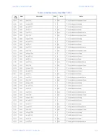
Страница 51: ...val Points Configured R Returns 0 if intervals are disabled 0011 0017 Number of Max Min Points Configured R Always returns 0 0012 0018 Maximum Number of Intervals That Can Be Recorded R Dependent upon the number of parameters optioned and the number of meters returned in address 0015 0013 0019 Number of slots configured for Scan Transponder R 0014 0020 Current slot being read in Scan Transponder W...

Страница 52: ...Bits Mask out ignore Bit 15 0 Data is ready for read 1 Populate registers with timestamp data 2 Invalid Timestamp Requested Stored Dynamic Data Ready for Read Average Interval Data 0063 0099 Interval Data Qualifying Register R 16 bit Unsigned Integer 8 Invalid Interval 0064 0100 Meter 1 Three Phase Total kW R kW Stored Interval 1 for Meter 1 0066 0102 Meter 1 Three Phase Total kvar R kvar Stored I...

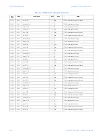
Страница 53: ...er 8 Three Phase Total Power Factor R Stored Interval 4 for Meter 8 00A4 0164 Meter 9 Two Phase Total kW R kW Stored Interval 1 for Meter 9 00A6 0166 Meter 9 Two Phase Total kvar R kvar Stored Interval 2 for Meter 9 00A8 0168 Meter 9 Two Phase Total kVA R kVA Stored Interval 3 for Meter 9 00AA 0170 Meter 9 Two Phase Total Power Factor R Stored Interval 4 for Meter 9 00AC 0172 Meter 10 Two Phase To...

Страница 54: ... Single Phase Total kVA R kVA Stored Interval 3 for Meter 17 00EA 0234 Meter 17 Single Phase Total Power Factor R Stored Interval 4 for Meter 17 00EC 0236 Meter 18 Single Phase Total kW R kW Stored Interval 1 for Meter 18 00EE 0238 Meter 18 Single Phase Total kvar R kvar Stored Interval 2 for Meter 18 00F0 0240 Meter 18 Single Phase Total kVA R kVA Stored Interval 3 for Meter 18 00F2 0242 Meter 18...

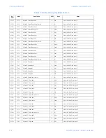
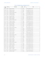
Страница 55: ...age A N R V Phase to Ground Instantaneous Voltage 016C 0364 Voltage B N R V Phase to Ground Instantaneous Voltage 016E 0366 Voltage C N R V Phase to Ground Instantaneous Voltage 0170 0368 Voltage CT01 R V CT 1 Instantaneous Voltage 0172 0370 Amps CT01 R A CT 1 Instantaneous Current 0174 0372 kW CT01 R kW CT 1 Instantaneous Power 0176 0374 kvar CT01 R kvar CT 1 Instantaneous Reactive Power 0178 037...

Страница 56: ...eous Apparent Power 01B6 0438 Voltage CT08 R V CT 8 Instantaneous Voltage 01B8 0440 Amps CT08 R A CT 8 Instantaneous Current 01BA 0442 kW CT08 R kW CT 8 Instantaneous Power 01BC 0444 kvar CT08 R kvar CT 8 Instantaneous Reactive Power 01BE 0446 kVA CT08 R kVA CT 8 Instantaneous Apparent Power 01C0 0448 Voltage CT09 R V CT 9 Instantaneous Voltage 01C2 0450 Amps CT09 R A CT 9 Instantaneous Current 01...

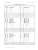
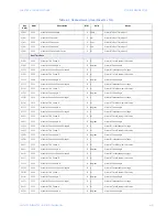
Страница 57: ...ntaneous Apparent Power 01FC 0508 Voltage CT15 R V CT 15 Instantaneous Voltage 01FE 0510 Amps CT15 R A CT 15 Instantaneous Current 200 0512 kW CT15 R kW CT 15 Instantaneous Power 0202 0514 kvar CT15 R kvar CT 15 Instantaneous Reactive Power 0204 0516 kVA CT15 R kVA CT 15 Instantaneous Apparent Power 0206 0518 Voltage CT16 R V CT 16 Instantaneous Voltage 0208 0520 Amps CT16 R A CT 16 Instantaneous ...

Страница 58: ...ous Power 023E 0574 kvar CT21 R kvar CT 21 Instantaneous Reactive Power 0240 0576 kVA CT21 R kVA CT 21 Instantaneous Apparent Power 0242 0578 Voltage CT22 R V CT 22 Instantaneous Voltage 0244 0580 Amps CT22 R A CT 22 Instantaneous Current 0246 0582 kW CT22 R kW CT 22 Instantaneous Power 0248 0584 kvar CT22 R kvar CT 22 Instantaneous Reactive Power 024A 0586 kVA CT22 R kVA CT 22 Instantaneous Appar...

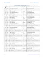
Страница 59: ...3 Three Phase kvar R kvar Meter 3 Real Time Input 4 02A8 0680 Meter 3 Three Phase kVA R kVA Meter 3 Real Time Input 5 02AA 0682 Meter 3 Three Phase Power Factor R Meter 3 Real Time Input 6 02AC 0684 Meter 4 Three Phase kWh R kWh Meter 4 Real Time Input 1 02AE 0686 Meter 4 Three Phase kvarh R kvarh Meter 4 Real Time Input 2 02B0 0688 Meter 4 Three Phase kW R kW Meter 4 Real Time Input 3 02B2 0690 M...

Страница 60: ...kvarh R kvarh Meter 9 Real Time Input 2 02EC 0748 Meter 9 Phase kW R kW Meter 9 Real Time Input 3 02EE 0750 Meter 9 Phase kvar R kvar Meter 9 Real Time Input 4 02F0 0752 Meter 9 Phase kVA R kVA Meter 9 Real Time Input 5 02F2 0754 Meter 9 Phase Power Factor R Meter 9 Real Time Input 6 02F4 0756 Meter 10 Phase kWh R kWh Meter 10 Real Time Input 1 02F6 0758 Meter 10 Phase kvarh R kvarh Meter 10 Real ...

Страница 61: ...put 1 0332 0818 Meter 15 Phase kvarh R kvarh Meter 15 Real Time Input 2 0334 0820 Meter 15 Phase kW R kW Meter 15 Real Time Input 3 0336 0822 Meter 15 Phase kvar R kvar Meter 15 Real Time Input 4 0338 0824 Meter 15 Phase kVA R kVA Meter 15 Real Time Input 5 033A 0826 Meter 15 Phase Power Factor R Meter 15 Real Time Input 6 033C 0828 Meter 16 Phase kWh R kWh Meter 16 Real Time Input 1 033E 0830 Met...

Страница 62: ...nput 6 0378 0888 Meter 21 Phase kWh R kWh Meter 21 Real Time Input 1 037A 0890 Meter 21 Phase kvarh R kvarh Meter 21 Real Time Input 2 037C 0892 Meter 21 Phase kW R kW Meter 21 Real Time Input 3 037E 0894 Meter 21 Phase kvar R kvar Meter 21 Real Time Input 4 0380 0896 Meter 21 Phase kVA R kVA Meter 21 Real Time Input 5 0382 0898 Meter 21 Phase Power Factor R Meter 21 Real Time Input 6 0384 0900 Me...

Страница 63: ...rees Meter 2 Phase Angle 03FE 1022 Meter 2 Phase to Phase Voltage A R V Meter 2 Instantaneous Voltage 0400 1024 Meter 2 THD Phase B R Meter 2 Total Harmonic Distortion 0402 1026 Meter 2 Phase Angle B R degrees Meter 2 Phase Angle 0404 1028 Meter 2 Phase to Phase Voltage B R V Meter 2 Instantaneous Voltage 0406 1030 Meter 2 THD Phase C R Meter 2 Total Harmonic Distortion 0408 1032 Meter 2 Phase Ang...

Страница 64: ...tage 0442 1090 Meter 6 THD Phase A R Meter 6 Total Harmonic Distortion 0444 1092 Meter 6 Phase Angle A R degrees Meter 6 Phase Angle 0446 1094 Meter 6 Phase to Phase Voltage A R V Meter 6 Instantaneous Voltage 0448 1096 Meter 6 THD Phase B R Meter 6 Total Harmonic Distortion 044A 1098 Meter 6 Phase Angle B R degrees Meter 6 Phase Angle 044C 1100 Meter 6 Phase to Phase Voltage B R V Meter 6 Instant...

Страница 65: ...8 Phase Angle 0476 1142 Meter 8 Phase to Phase Voltage C R V Meter 8 Instantaneous Voltage Counters 07D0 2000 Number of phases offset R 16 bit Unsigned Integer 1 2 3 or 24 phases available 07D1 2001 Demand Window Offset R 16 bit Unsigned Integer 5 15 or 30 minutes available 07D2 2002 I Multiplier Type Offset R 16 bit Unsigned Integer Internal calibration value 07D3 2003 Number of Pulse Counters Of...

Страница 66: ...4 24 EPM 4500 SUB METER INSTRUCTION MANUAL MODBUS MEMORY MAP CHAPTER 4 COMMUNICATIONS ...

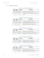
Страница 67: ...00 REVISION RELEASE DATE GEK 106555 1601 0157 A1 1 0x 10 June 2004 GEK 106555A 1601 0157 A2 1 0x 18 October 2004 GEK 106555B 1601 0157 A3 1 0x 1 December 2004 GEK 106555C 1601 0157 A4 1 0x 5 January 2005 GEK 106555D 1601 0157 A5 1 0x 14 February 2005 GEK 106555E 1601 0157 A6 1 0x 08 April 2005 GEK 106555F 1601 0157 A7 1 0x 20 February 2006 GEK 106555G 1601 0157 A8 1 0x 30 June 2006 GEK 106555H 160...

Страница 68: ...1 4 1 Update Updated RS485 WIRING FOR MODBUS section 4 2 Add Added RS232 WIRING FOR MODBUS section Table 5 4 Major Updates for 1601 0157 A7 PAGE A6 PAGE A7 CHANGE DESCRIPTION Title Title Update Manual part number to 1601 0157 A7 3 2 3 2 Update Updated EPM4500 DISPLAY STRUCTURE diagram Table 5 5 Major Updates for 1601 0157 A6 PAGE A5 PAGE A6 CHANGE DESCRIPTION Title Title Update Manual part number ...

Страница 69: ...HANGE DESCRIPTION Title Title Update Manual part number to 1601 0157 A3 4 3 4 3 Update Updated MODBUS ACTIVATION section Table 5 9 Major Updates for 1601 0157 A2 PAGE A1 PAGE A2 CHANGE DESCRIPTION Title Title Update Manual part number to 1601 0157 A2 2 2 Replace Replaced PHASE ROTATION section and example with updated PHASE ASSOCIATION section Phase rotation information is now included with the wi...

Страница 70: ...rned with all transportation charges prepaid to an authorized service centre or the factory Repairs or replacement under warranty will be made without charge Warranty shall not apply to any device which has been subject to misuse negligence accident incorrect installation or use not in accordance with instructions nor any unit that has been altered outside a GE Energy authorized factory outlet GE ...

Страница 71: ...4 3 CT INSTALLATION 2 15 CT MULTIPLIERS 3 4 CT ORDER CODES 1 9 CURRENT TRANSFORMER INSTALLATION 2 15 CURRENT VERIFYING 3 6 D DATA LOGGER 1 5 DEMAND RESETTING 3 7 DEMAND SPECIFICATIONS 1 5 DIMENSIONS 1 6 DISPLAY STRUCTURE 3 3 E ENERGY VERIFYING 3 6 ENVIRONMENTAL SPECIFICATIONS 1 6 G GETTING STARTED 1 1 I INSTALLATION CATEGORY 1 6 INTERIOR VIEW 1 3 INTERNAL FUSE BLOCK 2 17 M MCI BOARD WIRING 2 16 ME...

Страница 72: ...TIVE MAINTENANCE 1 4 PROTECTIVE CONDUCTOR TERMINAL 1 4 PROTOCOLS 1 6 PULSE INPUTS 1 9 R RESIDENTIAL METER 1 8 RS232 WIRING FOR MODBUS 4 2 RS485 WIRING FOR MODBUS 4 1 S SCAN TRANSPONDER functionality 1 2 installing 2 18 location 2 18 models 1 9 SHIPPING SPECIFICATIONS 1 6 SPECIFICATIONS 1 5 STAND ALONE METER 1 2 T TRANSIENT SURGE SUPRESSION 1 6 TYPE TESTS 1 6 U UL APPROVAL 1 7 USER INTERFACE 3 1 V ...

Страница 73: ...INDEX 3 VERIFYING VOLTAGE 3 5 VERTICAL MOUNTING OPTION 2 2 VOLTAGE VERIFYING 3 5 W WARNINGS 1 3 WARRANTY 5 4 WIRING 1 phase 3 wire 2 12 2 14 1 phase 3 wire 120 V 2 6 2 8 3 phase 3 wire delta 2 9 2 11 3 phase 4 wire wye 2 3 2 5 overview 2 2 ...

Страница 74: ...INDEX 4 EPM 4500 SUB METER INSTRUCTION MANUAL INDEX ...

Отзывы: