3
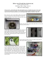
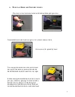
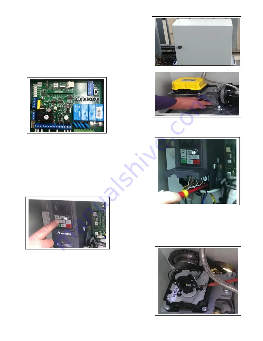
To commission the gate, move the gate approximately half
way and tighten the knurled wheel (Clockwise) engaging the
clutch assembly enough that it will drive the gate but will slip
if it accidentally hits its mechanical stop hard during set up
.
Make sure at end of set up that the clutch is tightened up
firm.
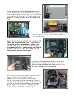
Press the opening button located under the dip switches to
begin opening cycle.
Ensure the direction the gate travels is in accordance with
the opening and closing status LED’s, if not reverse any
two of the motor wires at the inverter terminals. Then
adjust the slow speed switch cams around ensuring the
open cam switch activates in the open direction, and so too
the close cam for the close direction well before the gate
reaches it`s full open and closed positions.
Inverter settings can be adjusted if needed via the keypad i.e.
Opening speed, closing speed and ramp times. Automation
settings operating modes are able to be adjusted via the CB6
board, refer to manual for further instructions.
Once inverter settings are appropriately set, proceed to make
finer adjustments to the slow speed switches
Making sure the gate travels into its open and closed
mechanical stops at the slow speed and changes to its slow
speed at a comfortable distance before it reaches the final stop
positions. A larger gate will need a larger slow down area.
Don`t forget to set run motor run travel timing via the
run/set switch as described in commissioning.
Содержание GDS 450 W
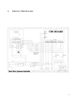
Страница 14: ...14 4 SCHEMATIC WIRING DIAGRAM ...
Страница 18: ......


