


2
Abbreviated Installation Instructions
(For those who don't have time!)
S l i d i n g G a t e O p e r a t o r s
GDS 450, 630 W Range
PLEASE NOTE – THE LIMIT SWITCHES WITH THIS RANGE OF OPERATORS ARE ONLY USED
TO CHANGE FROM FAST SPEED TO SLOW SPEED, THE OPERATOR IS DESIGNED TO DRIVE
THE GATE ONTO THE MECHANICAL STOPS WHERE THEN THE MOTOR WILL TURN OFF
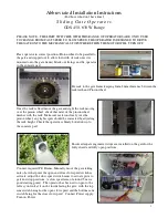
Place operator in correct position (Pinion wheel to be parallel to
the gate and stepped out to allow for width of rack once it is
mounted onto the gate frame). Mark out fixings and fix operator
to the concrete pad.
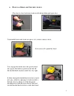
Fix rack to the gate frame keeping 1mm-2mm clearance between the
rack teeth and Pinion wheel
Once the rack is fixed move the gate and sight the rack moving
over the pinion wheel, check that most of the pinion wheel
meshes with the rack. Make sure rack runs freely over the
pinion wheel, any tights spots should be corrected by adjusting
the rack height. Check the operator is firmly bolted down to
the concrete pad.
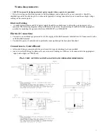
Ensure adequate engineered stops are installed on the gate for the
fully closed and fully open positions.
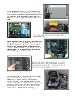
Connect required P.E Beams. Manually move the gate taking
note of at what point the open and close slow speed switches
activate, adjust the slow speed switch cams to actuate prior to
gate end stop positions. (a slow speed area of around .5m is a
good starting point). The operator has been set to open to the
left as you look at it on the inside facing the gate, with the top
cam switch being for the open slow speed and the bottom cam
switch being for the close slow speed. Connect Power supply.
Turn on Power.
Содержание GDS 450 W
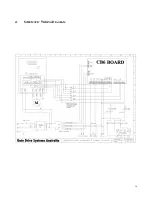
Страница 14: ...14 4 SCHEMATIC WIRING DIAGRAM ...
Страница 18: ......


