GASMAX/TX Operation & Maintenance Manual, Revision 1.0
Page 38
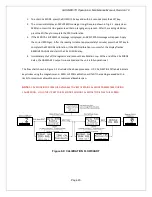
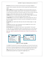
TRACK NEGATIVE
allows the display to show negative values when set to “YES”. This can be helpful when
troubleshooting sensor problems. The default setting is “NO” and forces the display to read “0” if the
sensor value drops below zero. However, negative sensor outputs will always cause the Fault alarm to
trip.
BACKUP CONFIG
allows users to store the entire current GASMAX/TX menu database into non-volatile
memory for restoration later if incorrect values are accidentally entered or uploaded.
RESTORE CONFIG
restores the GASMAX/TX menu database to the values from the most recent Backup
Config. The special keystroke sequence of 4 consecutive UP keys is also required to perform backup and
restore operations.
LOAD DEFAULTS
restores factory default settings.
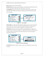
Figure 11-3: Alarm Settings Menu
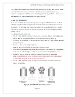
The Alarm Settings page covers the Alarm 1, 2 and 3 menu items. Alarm 1, Alarm 2, Alarm 3 and Fault
menus are identical and are therefore described only once in this section. For the GASMAX/TX, the alarm
settings not only control the status of the indicator LEDs, but also cause alarm conditions to occur in the
GDS-95 Wireless Alarm Station and C2/TX Wireless Site Monitor.
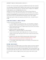
SET POINT
enters the engineering unit value where the alarm trips. It may be negative and trip when
monitored values fall out of range in this direction. Fault has a default setting of negative 10 with Low
Trip set for YES. It is important to adjust this value when the transmitter’s span value is set for another
value other than 100. For example, a typical span setting for monitoring oxygen level is 25 therefore the
fault level value should be adjusted to -2.5 which is equal to negative 10% of full scale.
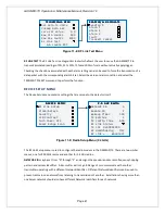
DEAD-BAND
has a minimum value of 1% and a maximum value of 10%. It is useful for preventing alarm
cycling when the monitored value is hovering around the set point. EXAMPLE: With a range of 0-100
ppm, if deadband equals 5% and the set point is 20 ppm, after tripping at 20 ppm the value must drop
below 15 ppm to reset.
LOW TRIP
set to YES causes the alarm to trip as the value falls below the set point.
ALARM SETTINGS
ALARM SETTINGS
ALARM SETTINGS
ALARM SETTINGS
ALARM 1 20.0
ALARM 2 40.0
ALARM 3 60.0
Fault -5.0
ALARM x SETUP
ALARM x SETUP
ALARM x SETUP
ALARM x SETUP
Set Point 20.0
Deadband 1%
Low Trip NO
Units ppm H2S
CHANNEL x
CHANNEL x
CHANNEL x
CHANNEL x
Channel ENABLED
Configure Readout
Alarm Settings
Sensor Information
Technicians Only
Sensor Temp 29.0C

