


GASMAX/TX Operation & Maintenance Manual, Revision 1.0
Page 21
7
INSTALLATION
LOCATING THE GASMAX/TX
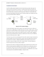
Factors such as air movement, gas density in relation to air, emission sources and environmental variables
affect correct sensor location. Air movement by fans, prevailing winds and convection should be carefully
evaluated to determine if a leak is more likely to raise gas levels in certain areas within the facility. Vapor
density of a gas determines if it will rise or fall in air when there are no significant currents. Lighter than
air gases should have the monitors mounted 12 – 18 inches (30 – 45 cm) above the potential gas leak and
heavier than air gases should be this distance below. Even though the GASMAX/TX is designed for rugged
service, sensors should be protected from environmental damage from water, snow, shock, vibration and
dust and dirt.
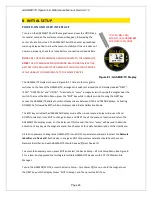
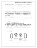
MOUNTING THE GASMAX/TX
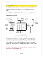
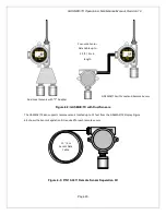
The GASMAX/TX standard enclosure is a cast aluminum explosion-proof
(NEMA 7) enclosure and should always be mounted with the sensor head
opening facing down. If necessary, a Splash Guard (p/n 10-0205) should be
attached if there is any chance that water or liquid spray could enter the
sensor opening from below. Be sure to leave sufficient room below the
sensor head to allow easy access for attachment of a Calibration Cup and /
or removal of the sensor head cover for sensor replacement.
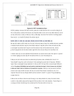
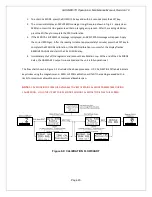
Whenever possible, the GASMAX/TX should be mounted in a location that
provides clear line-of-sight between the gas monitor and receiving antenna.
Both 900 MHz and 2.4 GHz signals will travel through masonry or wooden
structures with minimal loss; however, large metal buildings, tanks and
other solid structures will block the signal or attenuate the transmission to
the point where reliable wireless communications may not be possible. For
900 MHz radios, power levels can be adjusted from 10 mW up to 1.0 watt
(higher power will reduce battery life). In many cases, GDS-95 Wireless
Repeaters can be used to route wireless signals around obstacles.
Height above ground also affects wireless transmissions, and raising the
antenna at either end of the path will improve signal strength and reduce transmission errors. GDS Corp
recommends placing the central receiver antenna at least 10 feet about the surrounding terrain, and even
more if possible. However, note that standard vertical dipole antennas transmit their maximum signal
strength in a relatively flat ‘donut-shaped’ pattern which may affect the performance of GASMAX/TX
monitors located close to an elevated central antenna.
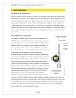
12” MIN for sensor
replacement and
calibraton
900 MHz
24” MIN
2.4 GHz
6” MIN
Distance from nearest
metallic surface


