GBC 620os
Operation Manual
© 2007 General Binding Corporation
Page 9
FEATURES/ACCESORIES GUIDE
Refer to the following pages for detailed
Features.
information on the
Figure 1
Fig
ure 2
Fig e 3
ur
Figure 4
ement. To disengage, turn the
EMERGENCY
atches
ensures that
serted properly and if not
perate.
afety Shield
prevents entanglement,
inadvertent contact with the
Heat Roller
.
is used to take up any film that is being slit
Slitters
.
he Nip. It
cording to the paper size selected on the
an even and accurate overlap.
images into the Feed Gate and
mG
)
ccurate
and film being used, the
to assist in the
mount
ator. The
Decurling Bar
is
lls
and the
Pull Rolls
.
te when the next sheet
eed Table.
Sheets should not be
inated.
The
Feed Gate Stops
can be adjusted up, down, and left to
right to accommodate various media paper thicknesses.
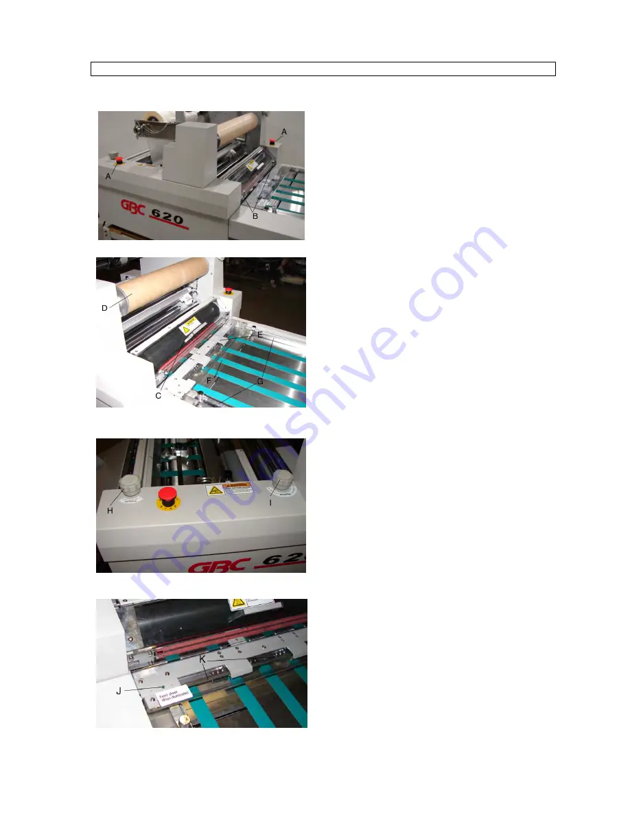
EMERGENCY STOP BUTTONS
(
Fig. 1– Item A
)
There are two
EMERGENCY STOPS
on the laminator.
One is located at the rear of the machine and the other is
located on the front.
To engage, press any
EMERGENCY STOP
to stop the
roller mov
STOP
clockwise after the emergency condition has been
resolved.
FRONT SAFETY SHIELD INTERLOCK LATCHES
(
Fig.1-Item B
)
The
Front Safety Shield Interlock L
the Front Safety Shield is in
achine will not o
engaged, the m
FRONT SAFETY SHIELD
Fig.2-ItemC
)
(
The
Front S
entrapment, and
REWINDER
Fig.2-ItemD
)
(
The
Rewinder
In-Line
via the
FEED GATE
(
Fig.2-ItemE
)
he
Feed Gate
controls the images entering t
T
will activate ac
e
display, and giv
FEED BELTS
Fig.2-ItemF
)
(
The
Feed Belts
move the
t
ip.
hen into the n
TABLE SIDE GUIDES
(
Fig.2-Ite
The
Table Side Guides
are adjustable to ensure a
feeding.
BURST ROLLER GAP ADJUSTMENT KNOB
(
Fig.3-ItemH
)
The
Burst Roller Gap Knob
raises and lowers the
Burst
oller.
Depending on the media
R
operator can raise or lower the
Burst Roller
ing of the images.
Burst or Snapp
DECURLING ADJUSTMENT KNOB
(Fig.3-ItemI)
The
Decurling Adjustment Knob
is used in conjunction
with the film shaft brake to increase or decrease the a
of curl desired by the oper
n the
Main Ro
located betwee
FEED INDICATOR LED
(Fig.4-ItemJ)
The
Feed Indicator LED
will indica
can be placed on the
F
LED is illum
placed until the
FEED GATE STOPS
(Fig.4-ItemK)


