42
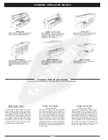
STANDARD VENTILATOR MODELS
STANDARD MAKE-UP AIR OPTIONS
The make-up air options shown below are available on all BDL Series Ventilators.
This method of introducing air into the hood is
typically referred to as the “short circuit” method.
This design has very limited applications and the
amount of supply air able to be introduced varies
considerably with the type of cooking equipment.
This air may be untempered air in most areas
depending upon climatic conditions and the type
of cooking equipment. The difference between
the quantity of air being introduced and the
amount of air being exhausted must be supplied
through a traditional make-up air system.
This method of introducing make-up air into the
kitchen is flexible and has many advantages.
Make-up air is discharged through stainless steel
perforated panels as illustrated (MAW Series) or
optional registers. Typical supply volume is 80%
of the exhaust or more, depending on air bal-
ance desired. Supply air temperatures should
range from 60 to 65°F (16 to 18°C), but may be
as low as 50°F (10°C) depending on air volume,
distribution, and internal heat load.
MODEL “MAW” SERIES
FRONT FACE DISCHARGE
MODEL “MAI” SERIES
INTERNAL DISCHARGE
This method of introducing air into the kitchen
area is typically used when “spot cooling” of the
kitchen staff is desired to help relieve the effects
of severe radiant heat generated from equipment
such as charbroilers. Discharge velocities must
be carefully engineered to avoid air turbulence
at the cooking surface, discomfort to personnel
and the cooling of foods. The amount of supply
air introduced may be up to 80% of exhaust de-
pending upon the type of cooking equipment in-
volved, and the air temperature should be 65° F
(18°C) or higher.
MODEL “MAP” SERIES
DOWN DISCHARGE
Содержание CG Series
Страница 25: ...MEASURING INLET SLOT VELOCITY 23 FIG 23A FIG 23B FIG 23C CROSS SECTION OF TYPICAL VENTILATOR INLET SLOTS ...
Страница 34: ...32 DETERGENT PUMP ...
Страница 35: ...33 MISCELLANEOUS VENTILATOR PARTS ...
Страница 36: ...34 WIRING DIAGRAM FOR GPC 5000 WITH ELECTRIC FIRE DAMPER 120 VOLT ...
Страница 37: ...35 WIRING DIAGRAM FOR GPC 5000 WITH FUSE LINK FIRE DAMPER 120 VOLT ...
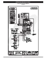
Страница 38: ...WIRING DIAGRAM FOR GPC 5000 S5 WITH ELECTRIC FIRE DAMPER 120 VOLT 36 ...
Страница 39: ...WITH FUSE LINK FIRE DAMPER 120 VOLT WIRING DIAGRAM FOR GPC 5000 S5 37 ...
Страница 40: ...WIRING DIAGRAM FOR GPC 5000 WITH ELECTRIC FIRE DAMPER 220 VOLT 38 ...
Страница 41: ...WITH FUSE LINK FIRE DAMPER 220 VOLT WIRING DIAGRAM FOR GPC 5000 39 ...
Страница 42: ...WIRING DIAGRAM FOR GPC 5000 S5 WITH ELECTRIC FIRE DAMPER 220 VOLT 40 ...
Страница 43: ...WITH FUSE LINK FIRE DAMPER 220 VOLT WIRING DIAGRAM FOR GPC 5000 S5 41 ...
Страница 46: ......


