INTERNAL FIRE MODE (CONTINUED)
On thermostatically activated systems, the water will run until
the thermostat cools below 280°F (138°C), and then continue
for a 5 minute cool down cycle. The water may be shut off prior
to the end of the 5 minute cool down cycle by pushing the
“Cancel” button located inside the electrical compartment of
the control cabinet. After the water has shut off, the dampers
can be reset by pulling the reset handle on the damper control
switch (Refer to Figure 11), and the exhaust fan(s) restarted by
pushing the “Start Fan” button on the Command Center.
EXTERNAL FIRE MODE
A break glass type fire switch is optional and if provided, would
normally be located at the exit of the kitchen. Pulling the fire
switch shuts off supply fan and starts the exhaust fanif it was
off, releases fire smothering water spray into the interior of the
ventilator, and the “Fire” light on the Command Center
flashes. During this time, the fire damper remains open, and
the exhaust fan remains on to help remove smoke, heat, etc.
If the fire intensified and the fuse link or thermostat reach
280°F(138°C), the fire damper would then close and the
exhaust fan would shut off.
To resume normal operations, open the fire switch and flip the
toggle switch to the position marked “normal”. (Refer to Figure
12) Replace the glass rod and close the cover.
FIG. 13
FIRE CYCLE
8
"RG" SERIES VENTILATOR PRINCIPLE OF OPERATION
FIG. 11
DAMPER CONTROL SWITCH
MODEL C-61-GXSH-RG
USED WITH THERMOSTATICALLY
ACTIVATED SYSTEMS
TESTING INTERNAL FIRE MODE
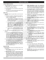
The internal fire protection system may be tested periodically
by pushing the “Fire Test Switch” which is located inside the
electrical compartment of the control cabinet. Pushing this
switch will cause the following:
Thermostatically Activated
Fuse Link Activated
1. Water turns on and
1. Water turns on and
will run for 5 minutes.
will run for 5 minutes.
2. Exhaust fan shuts off.
2. Exhaust fan shuts off.
3. Damper closes.
3. Fire light illuminates.
4. Fire light illuminates.
CAUTION: Before pushing the “Fire Test Switch”, check to
see if the internal fire protection system is tied to the building
alarm system.
TO RESUME NORMAL OPERATION
1.
To discontinue the 5 minute cool down cycle at any point
during the cycle, push the “Cancel” button located inside
the electrical compartment.
2.
Reset all damper control switches, if thermostatically
operated.
3.
Push the “Start Fan” button on the Command Center.
SURFACE FIRE PROTECTION
The Gaylord Ventilator may be equipped with surface fire
protection either dry or wet chemical, or the Gaylord Quencher
System. In the event of a fire, the surface fire protection
system would normally be activated and discharged prior to
the ventilator’s internal fire protection. These systems may be
intertied with the ventilator control cabinet to activate the
External Fire Mode. If the fire is unusually severe or the surface
fire protection system malfunctions, the ventilator’s internal
fire protection system would activate, thus providing a second
level of defense.
FIG. 12
BREAK GLASS FIRE SWITCH
C-1357A SERIES
FIRE DAMPER IN CLOSED POSITION
MELTED 280°F FUSE LINK
HINGED INSPECTION
DOOR
FIRE
QUENCHING
WATER SPRAY
DRAIN LINE
(OPTIONAL) SURFACE
FIRE PROTECTION
NOZZLE
Содержание CG Series
Страница 25: ...MEASURING INLET SLOT VELOCITY 23 FIG 23A FIG 23B FIG 23C CROSS SECTION OF TYPICAL VENTILATOR INLET SLOTS ...
Страница 34: ...32 DETERGENT PUMP ...
Страница 35: ...33 MISCELLANEOUS VENTILATOR PARTS ...
Страница 36: ...34 WIRING DIAGRAM FOR GPC 5000 WITH ELECTRIC FIRE DAMPER 120 VOLT ...
Страница 37: ...35 WIRING DIAGRAM FOR GPC 5000 WITH FUSE LINK FIRE DAMPER 120 VOLT ...
Страница 38: ...WIRING DIAGRAM FOR GPC 5000 S5 WITH ELECTRIC FIRE DAMPER 120 VOLT 36 ...
Страница 39: ...WITH FUSE LINK FIRE DAMPER 120 VOLT WIRING DIAGRAM FOR GPC 5000 S5 37 ...
Страница 40: ...WIRING DIAGRAM FOR GPC 5000 WITH ELECTRIC FIRE DAMPER 220 VOLT 38 ...
Страница 41: ...WITH FUSE LINK FIRE DAMPER 220 VOLT WIRING DIAGRAM FOR GPC 5000 39 ...
Страница 42: ...WIRING DIAGRAM FOR GPC 5000 S5 WITH ELECTRIC FIRE DAMPER 220 VOLT 40 ...
Страница 43: ...WITH FUSE LINK FIRE DAMPER 220 VOLT WIRING DIAGRAM FOR GPC 5000 S5 41 ...
Страница 46: ......


