


™
6
9
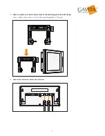
Installation of the Controller
9.1
Preparation
Install fixtures or ballasts according to your lighting plan. Follow the fixture or ballast manual instructions when connecting
them to the controller. If the fixture has a manual dimming knob, ensure that the knobs on all fixtures are set to "EXT" (external
control). Connect the fixtures to the power supply.
Each controller's two channels can control up to 256 e-Series fixtures or ballasts. These channels can control
luminaires in two separate rooms or up to 512 luminaires in a single room.
Warning!
Only connect EL3 controllers to compatible fixtures. For an up-to-date list of compatible
fixtures, visit gavita.com/EL3.
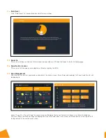
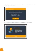
Please note that when installing the temperature sensor and controller, hang the sensor at average canopy height between
plants, preferably not against a wall.
If there is a sensor for your HVAC system, install the controller near the sensor for that system. If necessary, the sensor cable can
be extended by 5 meters using a standard 3.5 mm jack extension cable. Sensors with a cable length of 30 meters are
also available (HGC906196).
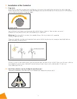
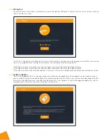
9.2
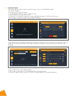
Install the controller’s cover by folding it around the sensor.
Light projected directly onto the sensor can interfere
with temperature measurements.
Wall
Wall
Wall
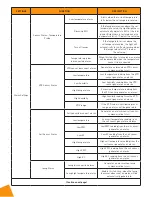
Output Power (W)