31
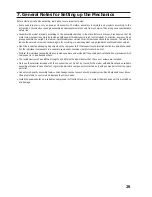
Page P.4
Upper figure:
After correctly aligning and screwing on the boom arms to the chassis plates, the seams between the chassis plates and
booms are glowed with liquid instant adhesive according to the figure.
Lower figure:
Insert the four speed controllers into the boom arms according to the drawing. The three-wire connection line with the servo
plug is guided through the central bore of the upper chassis plate. The two-wire power supply line with the BEC plug is
guided through the central bore of the lower chassis plate.
The speed controllers may be attached to the inside of the boom with double-sided adhesive tape (servo tape) after
assembly of the motors.
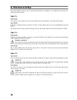
Page P.5
Upper figure:
The figure shows assembly of the drive motors and placement of the motor cables. The motor attachment screws are
secured with medium-hard threadlocker varnish.
Lower figure:
Connect the three motor connection lines to the connection lines of the speed controllers.
Important!
Connect the cables of the same colours for motors 1 and 3.
Swap the red and black cables of motors 2 and 4 so that the motors rotate in opposite directions.
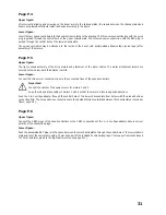
Push the 4-in-1 voltage adapter through the central bore of the lower chasses plate from below with the plus and minus
connection first. The plus and minus connections are then guided laterally outwards between the chassis plates (see upper
figure, page P.6).
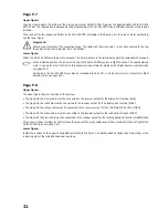
Page P.6
Upper figure:
Connect the 4 BEC plugs of the speed controllers to the 4 BEC connections of the 4-in-1 voltage adapter. Ensure correct
polarity of the connection plugs.
Lower figure:
Push the assembled BEC plug into the space between the two chassis plates through the central bore of the lower chassis
plate and cover the central bore with a 75 mm hook part of the included hook-and-loop tape. The loop part is also shortened
to 75 mm and later glued to the flight battery (also see page P.11).

