background image

CHAPTER 4: Installing Components

32

3

Select a Stripping Block size from the list at the top right of the screen.

4

Highlight the free disk you want to use from the list on the left side of the screen.

Содержание E-9232T

Страница 1: ... E 9232T Server USERGUIDE ...

Страница 2: ......

Страница 3: ...anager 13 Server security 14 Updating the baseboard management controller firmware 14 Using your Server Companion DVD 15 Server Companion DVD contents 15 Viewing documents 15 Installing drivers and programs 15 Booting the Server Companion DVD 16 Chapter 4 Installing Components 17 Preparing to install components 18 Selecting a place to work 18 Gathering the tools you need 18 Preventing static elect...

Страница 4: ...setting BIOS passwords 50 Updating or recovering the BMC 50 Updating or recovering the BMC firmware 50 Chapter 6 Troubleshooting 51 Telephone support 52 Before calling Gateway Customer Care 52 Telephone support 52 Tutoring and training 53 Safety guidelines 53 Error messages 53 Troubleshooting 57 First steps 57 Battery replacement 57 Beep codes 58 LED information 59 BIOS 60 Optical drive 60 Expansi...

Страница 5: ...iii www gateway com Memory map 66 Interrupts 66 Additional specifications 67 Appendix B BIOS Settings 69 Appendix C Legal Information 79 ...

Страница 6: ...Contents iv ...

Страница 7: ...CHAPTER1 1 Checking Out Your Gateway Server Front Back Interior System board Getting Help ...

Страница 8: ...CHAPTER 1 Checking Out Your Gateway Server 2 Front E 9232T Additional 5 25 inch drive bay DVD CD drive Power button Power indicator LED Diskette drive USB ports Additional 3 5 inch drive bay ...

Страница 9: ...ideo port Mouse port Power supply module PCI slots shown with EMI shields in place USB ports 4 Keyboard port NIC RJ 45 ports 2 Power supply voltage switch Kensington lock slot Cover release lever Rear chassis fan Power connector System management port RJ 45 ...

Страница 10: ...Checking Out Your Gateway Server 4 Interior Power supply module Front fan 5 25 inch drive bays Cover release latch Processor air duct Internal 3 5 inch drive bays 3 5 inch drive bays Memory slots Battery Back fan ...

Страница 11: ...ntation and product guides Technical tips and support Updated hardware drivers Order status Frequently asked questions FAQs Main power connector USB and NIC ports Power connector CMOS Battery PCI slot 5 Runs at 32 bits PCI slot 4 Runs at 32 bits PCI slot 3 PCI Express x8 Diskette drive connector Memory slots PCIe slot 1 PCI Express x16 PCIe slot 2 PCI Express x4 IDE connector USB and NIC ports Ser...

Страница 12: ...CHAPTER 1 Checking Out Your Gateway Server 6 ...

Страница 13: ...CHAPTER2 7 Setting Up Your Server Setting up the hardware Protecting from power source problems Starting your server Turning off your server Setting up the operating system Initial hardware settings ...

Страница 14: ... line noise than normal Line noise can also be a problem if your server is located near or shares a circuit with a device that causes electromagnetic interference such as a television or a motor Some uninterruptible power supplies include simple line conditioning capabilities Uninterruptible power supplies Use an uninterruptible power supply UPS to protect your server from data loss during a total...

Страница 15: ...settings for your specific network Selecting the boot device To select which device your server boots from 1 During server startup press F10 The Boot menu opens 2 Select the device you want to boot from Common choices include Removable Dev Removable device ATAPI CDROM CD or DVD drive Hard Drive NVIDIA Boot Agent Understanding the power on self test When you turn on your server the power on self te...

Страница 16: ...structions Initial hardware settings Your server comes from the manufacturer with the correct initial hardware settings to operate your server as configured However at some point you might want to change settings to reflect a tasking change a change in security requirements or the addition of new resources to your server General hardware settings as well as the onboard RAID solution can be changed...

Страница 17: ...CHAPTER3 11 Maintaining Your Server Caring for your server Preparing for system recovery System administration Updating the baseboard management controller firmware Using your Server Companion DVD ...

Страница 18: ... drive is installed A CD or DVD drive cleaning kit Cleaning tips Always turn off your server and other peripheral devices before cleaning any components Use a damp lint free cloth to clean your server and other parts of your server system Do not use abrasive or solvent cleaners because they can damage the finish on components Keep the cooling vents free of dust With your server turned off and unpl...

Страница 19: ...gency repair diskette to back up critical operating system files See your operating system s documentation or online help for instructions on using an emergency repair diskette Recording the BIOS configuration To help keep track of your custom changes to BIOS settings and to prepare for system recovery you should record your BIOS configuration after you have your server set up and working To recor...

Страница 20: ...ld blank then press ENTER The password is removed Updating the baseboard management controller firmware The baseboard management controller BMC performs several system management functions such as Monitoring server components FRU and sensor data records SDR the information provided depends on the option selected Managing non volatile storage for the system event log and sensor data records Interfa...

Страница 21: ...he document you want to view The document opens 4 To access files manually open the Docs Manuals folder on the Server Companion DVD To install Acrobat Reader 7 Click the link for Acrobat on the Documentation page OR Run Docs Reader app21279 Setup exe from the Server Companion DVD Installing drivers and programs You can install drivers and programs directly onto the server by using the Server Compa...

Страница 22: ... Extract Follow any on screen instructions To access the files manually Open the Drivers folder on the Server Companion DVD then open the appropriate subfolder Booting the Server Companion DVD By booting the Server Companion DVD you can re install the operating system repair applications and drivers or exit to the command prompt To boot to this DVD 1 With your server turned on insert the Server Co...

Страница 23: ...lectricity discharge Accessing the internal components Installing drives Configuring your onboard RAID solution Installing memory Installing PCI expansion cards Replacing the processor Replacing a power supply module Replacing a fan Replacing the CMOS battery Replacing the system board ...

Страница 24: ...with server components follow these guidelines Turn off the server then unplug the power cords and all other cables Press the power button to drain any residual power from the server Wear a grounding wrist strap available at most electronics stores and attach it to a bare metal part of the server You can also touch a bare metal surface on the back of the server with your finger Avoid static causin...

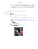
Страница 25: ...emely sensitive to static electricity make sure that you follow the instructions at the beginning of this chapter to avoid static electricity damage To open the server case 1 Follow the instructions in Preventing static electricity discharge on page 18 2 Turn off the server then unplug the power cords and all other cables connected to the server 3 Remove the case cover thumbscrew 4 Lift the cover ...

Страница 26: ... remove the bezel assembly 1 Follow the instructions in Opening the server case on page 19 2 After removing the side panel press the three black plastic tabs positions indicated by the arrows to release the right side of the bezel 3 Swing the right side of the bezel out until the left side of the bezel can be disengaged from the left side of the computer then remove the bezel ...

Страница 27: ...he instructions in Preventing static electricity discharge on page 18 2 Follow the instructions in Opening the server case on page 19 3 Remove the cables from the air duct cable clip 4 Grasp the air duct handle and remove the processor air duct from the chassis Processor air duct Air duct handle ...

Страница 28: ...s on the bottom of the air duct into the installation holes in the side of the chassis 2 Press the processor air duct into place 3 Place the diskette cable and hard drive power cable behind the cable clip on the processor air duct Important Be careful not to snag or unplug the fan cable when you install the processor air duct Processor air duct installation tabs Processor air duct installation hol...

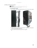
Страница 29: ...uter 2 Swing the right side of the bezel in to insert the tabs on the right side of the bezel into the slots on the right side of the computer 3 Press the right side of the bezel firmly until it snaps into place Important If you have installed any new drives in the external drive bays make sure to remove the corresponding filler panels in the bezel before installing it ...

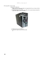
Страница 30: ...internal cables are arranged inside the case so they will not be pinched when you close the case 2 Align the panel tabs into the bottom case notches then swing the side panel toward the top of the computer to secure it into place 3 Replace the case cover thumbscrew 4 Reconnect the power cords and all other cables ...

Страница 31: ... If cable select is available drive assignments will be marked on the cable the IDE cable assigns the master slave positions to the drives it connects You can override these assignments using the jumpers on the drives If cable select is not available and only one drive is attached to an IDE controller cable configure the drive as master if it is a CD or DVD drive If two drives of any type are atta...

Страница 32: ...the drive bay allowing it to protrude enough to line up with the bezel when it is replaced then push the green drive retainer lever toward the front of the drive bay to lock the drive into place 10 Connect the power and data cables 11 Follow the instructions on Installing the bezel assembly on page 23 12 Follow the instructions in Closing the server case on page 24 Important If you are installing ...

Страница 33: ...he drive bay then pull the drive out of the bay 6 Set any jumpers on the new drive See the drive s documentation for further instructions 7 Slide the new drive into the drive bay as far as it will go then slide the green drive retainer lever toward the back of the drive bay to lock the drive into the bay 8 Connect the power and data cables 9 Follow the instructions in Closing the server case on pa...

Страница 34: ...quires high performance High data throughput for large files No fault tolerance Data is lost if a drive fails One or two on this server No 1 Data duplicated on another disk mirroring Use for read intensive fault tolerant systems 100 percent data redundancy providing fault tolerance More disk space required Reduces usable disk space to the size of the smallest drive Reduced performance during rebui...

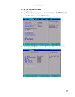
Страница 35: ...onsole 1 Restart your server 2 Press F2 when the Gateway logo screen appears during startup The BIOS Setup utility opens 3 From the Main BIOS menu select the Advanced menu 4 Select the Integrated Devices sub menu The Integrated Devices sub menu opens ...

Страница 36: ...ration option click Enabled 7 Select the SATA channels your hard drives are connected to and set them to Enabled 8 Exit the BIOS Setup utility 9 Restart your server During the boot process you will see the following message 10 Press F10 The RAID BIOS console opens 11 Configure the RAID options then exit the RAID BIOS console 12 Reboot the server ...

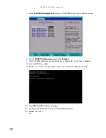
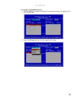
Страница 37: ... com 31 To configure the SATA RAID solution 1 Open the RAID BIOS console as described in the previous procedure The Define a New Array screen opens 2 Select a RAID Mode from the list at the top left of the screen ...

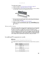
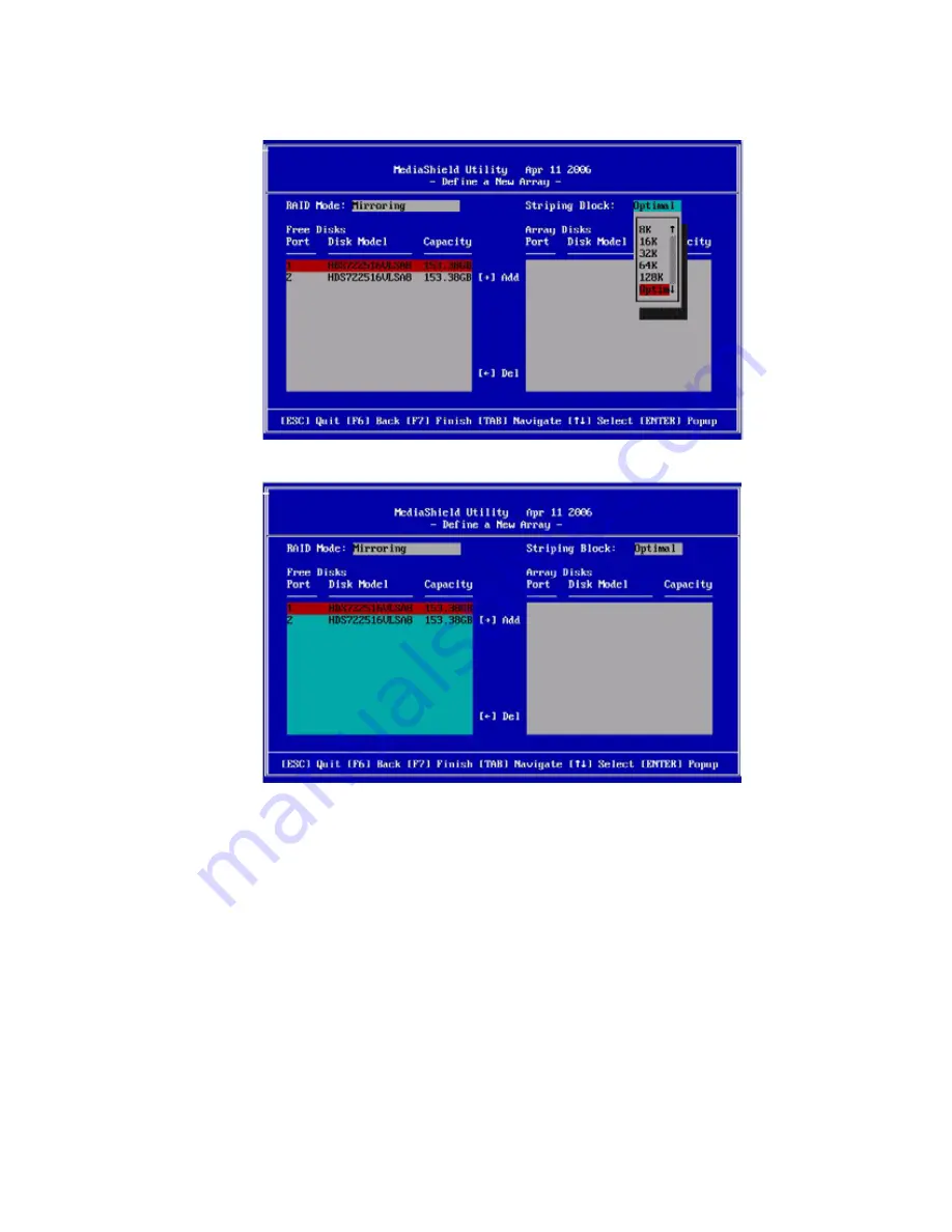
Страница 38: ...CHAPTER 4 Installing Components 32 3 Select a Stripping Block size from the list at the top right of the screen 4 Highlight the free disk you want to use from the list on the left side of the screen ...

Страница 39: ...ow key to move the disk to the Array Disks list on the right side of the screen Do this for all disks you want to use in the array 6 Press F7 to finish creating the array When the confirmation box opens press Y to clear the data on the disks ...

Страница 40: ...rted DIMM sizes include 256 MB 512 MB 1 GB and 2 GB The BIOS configures the memory controller to run in either single channel or dual channel mode depending on the following If one or more fully populated DIMM banks are detected the memory controller will run in dual channel mode If only a single DIMM is present the memory controller will run in single channel mode DIMM banks must be populated usi...

Страница 41: ...event data loss in case of DIMM failure If a DIMM failure does occur a DIMM fault LED adjacent to the DIMM slot will light orange to indicate the failed memory module Using memory online sparing one DIMM per channel selectable in the BIOS setup utility is used as a memory spare the spare DIMM must be equal to or larger than the largest DIMM in that channel If a DIMM begins to fail the contents of ...

Страница 42: ...ld card 4 Loosen the captive thumbscrew on the card retention bar and swing the bar out from the back of the chassis 5 If you are replacing a card remove the old expansion card To loosen the card you can slightly rock the card end to end but do not bend the card sideways Caution Do not touch the contacts on the bottom part of the expansion card Touching the contacts can cause electrostatic damage ...

Страница 43: ...nto the expansion slot To help insert the card you can slightly rock the card end to end but do not bend the card sideways 7 Swing the card retention bar back into place and tighten the captive thumbscrew Card retention bar Captive thumbscrew ...

Страница 44: ...instructions see Updating the BIOS on page 48 2 Follow the instructions in Preventing static electricity discharge on page 18 Make sure that you turn off the server then unplug the power cord s and all other cables connected to the server 3 Follow the instructions in Accessing the internal components on page 19 4 Loosen the four screws holding the heatsink to the processor then lift the heatsink o...

Страница 45: ...new processor into the socket making sure that the gold triangle on the corner is situated as shown in the following illustration Caution The processor only fits the socket when oriented as indicated Do not force the processor into the socket to avoid bending the pins or damaging the processor If the processor does not fit completely check its orientation and check for bent pins Gold triangle ...

Страница 46: ...upply module to identify the failed module The power supply module has failed if the orange right LED indicator is on 3 Unplug the power cord from the failed power supply module Caution The heatsink has Thermal Interface Material TIM located on the bottom of it Use caution when you unpack the heat sink so you do not damage the TIM If you are reusing the original heatsink make sure that the TIM on ...

Страница 47: ...on the power supply module grasp the handle and pull the module straight out from the server 5 Slide the new power supply module into the empty power supply bay until the green latch snaps into place 6 Plug the power cord into the new power supply module ...

Страница 48: ...e tab then disengage the fan and move it away from the chassis 6 Pull the fan from the chassis 7 Insert the new fan into the opening left by the old fan then insert the fan retention tabs and fan release tab into the chassis until it snaps into place 8 Plug the fan cable into the fan connector on the system board 9 Replace the processor air duct by following the instructions in Installing the proc...

Страница 49: ... in Closing the server case on page 24 Replacing the CMOS battery If the server clock does not keep time or the settings in the BIOS Setup utility are not saved when you turn off the server replace the CMOS battery with an equivalent battery To replace the battery 1 Print the appendix for BIOS Settings in this guide 2 Follow the instructions in Opening the BIOS Setup utility on page 48 Important M...

Страница 50: ...Press F2 when the Gateway logo screen appears during startup The BIOS Setup utility opens 13 Restore any BIOS settings that you wrote down in Step 3 14 Save all your settings and close the BIOS Setup utility Replacing the system board To replace the system board 1 Follow the instructions in Preventing static electricity discharge on page 18 2 Follow the instructions in Opening the server case on p...

Страница 51: ...he instructions in Installing memory on page 34 13 Reinstall the processor and heatsink by following the instructions in Replacing the processor on page 38 14 Connect the power and data cables 15 Reinstall the expansion cards by following the instructions in Installing PCI expansion cards on page 35 16 Follow the instructions in Closing the server case on page 24 17 Turn on your server 18 Press F2...

Страница 52: ...CHAPTER 4 Installing Components 46 ...

Страница 53: ...CHAPTER5 47 Using the BIOS Setup Utility Opening the BIOS Setup utility Updating the BIOS Recovering the BIOS Resetting BIOS passwords Updating or recovering the BMC ...

Страница 54: ...es you access to settings related to system access passwords For more information see Server security on page 14 Server gives you access to settings for system management console redirection event log configuration and fault resilient boot settings Exit gives you access to options for closing the BIOS Setup utility Updating the BIOS To update the BIOS 1 Print the appendix for BIOS Settings on page...

Страница 55: ... discharge on page 18 Make sure that you turn off the server then unplug the power cord s and all other cables connected to the server 2 Follow the instructions in Opening the server case on page 19 3 Remove the jumper across pins 1 2 of header J5 and place the jumper across pins 2 3 as shown in the illustration 4 Follow the instructions in Closing the server case on page 24 5 Insert the recovery ...

Страница 56: ... the power cords and turn on the server The BIOS password s is cleared 6 Turn off the server then disconnect the power cords and all other cables connected to the server 7 Follow the instructions in Opening the server case on page 19 8 Place the jumper back onto pins 1 2 9 Follow the instructions in Closing the server case on page 24 Updating or recovering the BMC Updating or recovering the BMC fi...

Страница 57: ...CHAPTER6 51 Troubleshooting Telephone support Tutoring and training Safety guidelines Error messages Troubleshooting ...

Страница 58: ...iled description of your issue including the exact text of any error messages and the steps you have taken Make sure that your server is nearby at the time of your call The technician may have you follow appropriate troubleshooting steps Consider using Gateway s online technical support Gateway s Web site has FAQs tips and other technical help You can also use the Web site to e mail Customer Care ...

Страница 59: ...en indicate procedural errors such as typing an incorrect keystroke or trying to save a file to a write protected diskette Some messages however may indicate a problem that requires further troubleshooting Memory messages Gate20 Error The BIOS is unable to correctly control the system board s Gate A20 function which controls access of memory over 1 MB This may indicate a problem with the system bo...

Страница 60: ...I devices in POST Secondary Master Hard Disk Error The IDE ATAPI device configured as Secondary Master could not be correctly initialized by the BIOS This message is typically displayed when the BIOS is trying to detect and configure IDE ATAPI devices in POST Secondary Slave Hard Disk Error The IDE ATAPI device configured as Secondary Slave could not be correctly initialized by the BIOS This messa...

Страница 61: ...onfiguration messages DMA 2 Error Error initializing secondary DMA controller This is a fatal error often indication a problem with system hardware DMA Controller Error POST error while trying to initialize the DMA controller This is a fatal error often indication a problem with system hardware Checking NVRAM Update Failed BIOS could not write to the NVRAM block This message appears when the FLASH...

Страница 62: ...This may indicate a problem with system hardware CMOS messages CMOS Date Time Not Set The CMOS Date and or Time are invalid This error can be resolved by readjusting the system time in AMIBIOS Setup CMOS Battery Low CMOS Battery is low This message usually indicates that the CMOS battery needs to be replaced It could also appear when the user intentionally discharges the CMOS battery CMOS Settings...

Страница 63: ...am see its documentation or online help Battery replacement If you have problems after installing a new CMOS battery try each of the following items closing the case and restarting the server after each try Restart your server then open the BIOS Setup utility by pressing and holding F2 while your server restarts Correct any discrepancies Remove the top panel by following the instructions in Openin...

Страница 64: ... system board malfunction To eliminate the possibility of an add in card problem remove all expansion cards If the beep code occurs even when all expansion cards have been removed the system board is at fault If the beep code does not occur when the expansion cards have been removed one of the cards is causing the problem Install the cards one at a time until the problem happens again When the bee...

Страница 65: ...drive fault Red Blinking Hard drive rebuilding Off No hard drive access NIC status LEDs Identify NIC states Control panel and back I O panel RJ 45 connectors Blue front Green Orange back Blue On Link Blue Blink Activity Off No link LED 1 Green On NIC linked LED 1 Green Blinking NIC 1 Gbps activity LED 1 Off No link LED 2 Orange On Link speed 1 Gbps LED 2 Green On Link at 100 Mbps LED 2 Green Off L...

Страница 66: ...blem happens frequently while the server is turned on the drive may be defective Expansion cards Your server does not recognize an expansion card Restart your server Make sure that you have installed the necessary software or driver For instructions see the card s documentation Reseat the expansion card and riser card For instructions see Installing PCI expansion cards on page 35 Hard drive The ha...

Страница 67: ...ke sure that you do not have a problem with your modem Keyboard Liquid has been spilled into the keyboard If you spilled liquid in the keyboard turn off your server and unplug the keyboard Clean the keyboard and turn it upside down to drain it Let the keyboard dry before using it again If the keyboard does not work after it dries you may need to replace it This type of damage is not covered by you...

Страница 68: ...nction Power You press the power button but the server does not turn on If the power button LED is green the server is turned on but you may not be seeing an image on the monitor For monitor troubleshooting see Monitor on page 61 If your server is plugged into a surge protector or UPS make sure that the surge protector or UPS is connected securely to an electrical outlet turned on and working corr...

Страница 69: ...APPENDIXA 63 Server Specifications ...

Страница 70: ...al drives 3 5 inch diskette CD ROM CD R or DVD ROM Tape drive Hard Drives Support for as many as four 3 5 SATA SATA II or SAS drives Supports full height PCI expansion cards up to 10 8 inches 27 5 cm long Power supply modules Single 400 W fixed power supply standard or Two 520 W hot swap redundant power supply modules optional Operating systems Red Hat Linux Enterprise 4 0 32 64 bit Editions SuSe ...

Страница 71: ...rd Marvel Ethernet NIC 10Base T 100Base TX 1000Base T PXE support ACPI ACPI compliance Supports S0 and S4 Hardware Monitor Main logic board sensors Voltage sensors Temperature sensors Adaptive fan speed control and fan speed detection Variable Requirements Temperature Maximum rate of change 18 F 10 C per hour Nonoperating 4 to 140 F 20 to 60 C Operating 41 to 95 F 5 to 35 C derated 0 9 F 0 5 C for...

Страница 72: ... card BIOS and buffer area 0E0000h to 0FFFFFh 128 KB System BIOS 0E0000h to 0EFFFFh 2 MB Extended system BIOS FC000000h to FFFFFFFFh 64 MB PCI memory space Important If you disable an IDE controller to free the interrupt for that controller you must physically unplug the IDE cable from the system board Simply disabling the drive by configuring the BIOS does not make the interrupt available Interru...

Страница 73: ...dditional Gateway documentation and detailed specifications for your own server IRQ14 Primary ATA legacy mode PIRQA USB 1 1 controller 1 and 4 PIRQB Video PIRQC USB 1 1 controller 3 Native IDE SATA PIRQD USB 1 1 controller 2 PIRQE Option for SCI TCO HPET 0 1 2 PIRQF Option for SCI TCO HPET 0 1 2 PIRQG Option for SCI TCO HPET 0 1 2 PIRQH USB 2 0 EHCI controller 1 Option for SCI TCO HPET 0 1 2 Ser I...

Страница 74: ...APPENDIX A Server Specifications 68 ...

Страница 75: ...APPENDIXB 69 BIOS Settings ...

Страница 76: ...tup The BIOS Setup utility opens 3 Select menus and submenus to display setting information Caution Setting the wrong values in the Advanced Menu may cause the server to malfunction BIOS menu BIOS submenu Setting Value Main System Overview AMIBIOS Version Build date System ID Version Processor Type Speed Count System Memory Size System Time HH MM SS System Date DAY MM DD YYYY Advanced CPU Configur...

Страница 77: ...isabled Device 0 Device 0 1 Device 0 1 2 nVidia RAID Setup Selects RAID Setup sub menu Primary IDE Master auto detected Selects IDE Configuration sub menu Primary IDE Slave auto detected Selects IDE Configuration sub menu Serial ATA 0 Primary Channel auto detected Selects IDE Configuration sub menu Serial ATA 0 Secondary Channel auto detected Selects IDE Configuration sub menu Serial ATA 1 Primary...

Страница 78: ...uration Onboard Floppy Controller Disabled Enabled Floppy A Disabled 1 44 MB 3 2 88 MB 3 Serial Port 1 Address Disabled 3F8 2F8 3E8 2E8 Serial Port 1 IRQ IRQ3 IRQ4 IRQ10 IRQ11 PS 2 Keyboard Present PS 2 Mouse Present IPMI 2 0 Configuration Nothing shown Remote Access Configuration Nothing shown USB Configuration USB Devices Enabled List of USB devices detected by BIOS Legacy USB Support Disabled E...

Страница 79: ... ROM Disabled Enabled PCIe Port1 Option ROM Disabled Enabled PCIe Port2 Option ROM Disabled Enabled PCIe Port3 Option ROM Disabled Enabled PCI X Port1 ROM Disabled Enabled Boot Boot Settings Configuration Quick Boot Disabled Enabled Quiet Boot Disabled Enabled Wait For F1 If Error Disabled Enabled Hit F2 Message Delay Disabled Enabled Boot Device Priority 1st Boot Device Varies Specifies boot sequ...

Страница 80: ...available devices nth Drive Varies Specifies boot sequence from the available devices Security Supervisor Password Installed Not installed User Password Installed Not installed Change Supervisor Password Set or clear Supervisor password User Access Level No Access View Only Limited Full Access Change User Password Set or clear User password Password Check Disabled Enabled Boot Sector Virus Protect...

Страница 81: ...ST Disabled Boot Loader Always Terminal Type ANSI VT100 VT UTF8 VT UTF8 Combo Key Support Disabled Enabled IPMI Configuration Status of BMC BMC Firmware Revision View BMC Event Log Provides data on event log Clear BMC System Event Log Disable PEF No Yes Restore on AC Power Loss Power Off Power On Last State Wake on RING function Disabled Enabled Exit Save Changes and Exit F10 Discard Changes and E...

Страница 82: ... Secondary Channel Enabled Disabled BIOS submenu BIOS 2nd level submenu Setting Value IDE Configuration Primary IDE Master All IDE drives Below is shown information and options appropriate to drive type Device Device information Vendor Device vendor Size Device size LBA Mode Device LBA mode Block Mode Device block mode PIO Mode Device PIO mode Async DMA Device Async DMA mode Ultra DMA Device Ultra...

Страница 83: ...rage Device Configuration USB Mass Storage Reset Delay 10 Sec 20 Sec 30 Sec 40 Sec Device 1 Only displayed if a device is detected Includes a DeviceID string returned by the USB device Emulation Type Auto Floppy Forced FDD Hard Disk CDROM Device n Only displayed if a device is detected Includes a DeviceID string returned by the USB device Emulation Type Auto Floppy Forced FDD Hard Disk BIOS submen...

Страница 84: ...APPENDIX B BIOS Settings 78 ...

Страница 85: ...APPENDIXC 79 Legal Information ...

Страница 86: ...ordampererating IfyoursystemisfittedwithaTVTuner cable orsatellitereceivercard makesurethattheantennaorcablesystemiselectricallygroundedtoprovidesomeprotectionagainstvoltagesurges andbuildupofstaticcharges Care during use Donotwalkonthepowercordorallowanythingtorestonit Donotspillanythingonthesystem SomeproductshaveareplaceableCMOSbatteryonthesystemboard ThereisadangerofexplosioniftheCMOSbatteryis...

Страница 87: ...as thesumofRENsshouldnotexceedfive 5 0 Tobecertainofthenumberofdevicesthatmaybeconnectedtoaline asdeterminedby thetotalRENs contactthelocaltelephonecompany Ifthisdevicecausesharmtothetelephonenetwork thetelephonecompanywillnotifyyouinadvancethattemporarydiscontinuanceofservicemayberequired Thetelephonecompanymay requestthatyoudisconnecttheequipmentuntiltheproblemisresolved Thetelephonecompanymayma...

Страница 88: ...etelecommunicationscompanycausetorequesttheusertodisconnecttheequipment Usersshouldmakesure fortheirownprotection thattheelectricalgroundconnectionsofthepowerutility telephonelines andinternalmetallicwaterpipesystem ifpresent areconnected together Thisprecautionmaybeparticularlyimportantinruralareas TheRingerEquivalenceNumber REN assignedtoeachterminaldeviceprovidesanindicationofthemaximumnumberof...

Страница 89: ...randouterpackaging includingshippingcontainers thisproductwasdeliveredin andbydisposingoforrecyclingusedbatteriesproperly Withyourhelp wecanreducetheamountofnaturalresourcesneededtoproduceelectricalandelectronicequipment minimizetheuseoflandfillsforthedisposalof endoflife products and generallyimproveourqualityoflifebyensuringthatpotentiallyhazardoussubstancesarenotreleasedintotheenvironmentandare...

Страница 90: ...APPENDIX C Legal Information 84 ...

Страница 91: ...rk 3 parallel 3 power 3 RJ 45 3 serial 3 USB 2 3 VGA 3 control panel location 2 cover panel removing 19 replacing 24 cover release latch location 2 D DDR SDRAM see memory device drivers installing 15 DIMM see memory diskette drive installing 25 27 location 2 replacing 25 27 display troubleshooting 61 documentation Gateway Web site 5 Server Companion DVD 15 drive bays location 2 drivers installing ...

Страница 92: ...r cleaning 12 port 3 troubleshooting 61 motherboard see system board mouse port 3 N network jack 3 NMI 57 non maskable interrupt 57 O onboard RAID configuring 28 onboard SATA RAID 28 online memory sparing 35 opening case 19 operating system setting up 10 optical drive troubleshooting 60 P parallel port 3 password resetting BIOS 50 supervisor 14 user 14 ports see connections POST power on self test...

Страница 93: ...screw location 3 system board LEDs 59 system configuration protecting with passwords 14 system interrupts 66 system recovery recording BIOS configuration 13 T tape drive cleaning 13 technical support Customer Care 52 resources 52 tips before contacting 52 telephone support 52 training CD 53 Gateway Learning Libraries 53 troubleshooting add in card 60 battery 57 beep codes 58 BIOS 60 card 60 error ...

Страница 94: ...88 www gateway com ...

Страница 95: ......

Страница 96: ...A MAN E 9232T USR GDE R1 9 07 8512069 Back fm Page 8 Wednesday August 29 2007 3 28 PM ...

Отзывы: