


3 – Installation & Wiring
T1 CrossConnect Installation & Operation Manual
Version 2
GatesAir
3-9
Intraplex Products
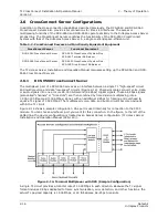
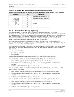
To manage a CM-95 (DCS) module and one CM-5 module from a PC (in a DCS-9560 or a DCS-9565),
perform these steps:
1.
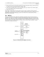
Insert an RJ-11 plug into the RS-232/RS-485 remote port on the MA-251A.
2.
Connect the other end of the phone jack cable to your PC using the RJ-11 to DB-9 adapter
provided.
3.
Use Table 3-8 to set the RJ-11 jack pin assignments.
4.
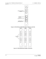
Insert an RJ-11 plug into the RS-232/RS-485 remote port on the MA-216.
5.
Use Table 3-7 to set the RJ-11 jack pin assignments.
6.
Connect the other end of the phone jack cable to the RS-485 port on the MA-251A.
7.
Use Table 3-9 to set the RJ-11 jack pin assignments.
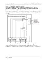
To manage a CM-95 (DCS) module and two CM-5 modules from a PC (in a DCS-9565), perform these
steps:
1.
Insert an RJ-11 plug into the RS-232/RS-485 remote port on the MA-251A.
2.
Connect the other end of the phone jack cable to your PC using the RJ-11 to DB-9 adapter
provided.
3.
Use Table 3-8 to set the RJ-11 jack pin assignments.
4.
Insert an RJ-11 plug into the RS-232/RS-485 remote port on the MA-216 of each CM-5 module.
5.
Use Table 3-7 to set the RJ-11 jack pin assignments.
6.
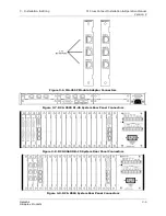
Connect the other end of each phone jack cable to a port in the modular T-junction.
7.
Take the fourth phone jack cable and insert it into a port in the modular T-junction provided.
8.
Connect the other end of the phone jack cable to the RS-485 port on the MA-251A.
9.
Use Table 3-9 to set the RJ-11 jack pin assignments.
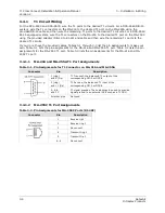
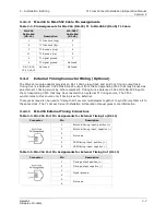
3.4.3.1 MA-216 Remote Port
The RS-232 pins (pins 2 and 4) provide the remote port for ISiCL commands to the CM-5. (ISiCL, the
Intraplex Simple Command Language (pronounced “icicle”) provides the basis for communication
between the user and the multiplexer. The operator types ISiCL commands at the keyboard and views
the responses on the terminal screen. Section 6 – “Configuration Using ISiCL” discusses how to use
this language.) The RS-485 pins (pins 1 and 6) provide daisy-chain connection for the remote port
signals to multiple multiplexers at one location.
Table 3-7. Pin Assignments for MA-216 Remote Port (RJ-11)
Connector
Pin
Description
1
RS-485 negative (-)
2
RS-232 transmit
3
Not used
4
RS-232 receive
5
Signal ground
6
RS-485 positive (+)
Содержание Intraplex T1 DCS-9530 CrossConnect System
Страница 2: ......


