background image


                                           MC2000 USER GUIDE 


11 


3. 4 - 

CALIBRATION: 

 
Each machine is factory-calibrated and is ready to operate on delivery.  However, the crimper 
must be tested each month and whenever the crimped diameter does not match the specified 
diameter.  The calibration procedure is as follows: 
 

Calibrate using –08 Megacrimp calibration shell 8G (7482-19860-5) 

 
-   Place die set no. 33 into the machine. 
-   Set the gauge to 200.


-   Crimp the calibration shell. 
-   Measure the calibration shell diameter - it should be 26.0mm +/- 0.25mm. 
-   If the crimped diameter matches the specified diameter, the machine is properly calibrated 
-


If the crimped diameter does not match the specified diameter, it is necessary to 
 

calibrate the machine as follows: 


1 -   Calculate  in  millimeters  the  difference between the crimped diameter and the 

calibration diameter of 26.0 mm 

2 -   Open the crimping head to its maximum 


3 -   Unscrew the two M6 screws which hold the stop strip on the back of the piston  


(Fig. 2 / 2) then remove the strip (Fig. 2 / 13). 

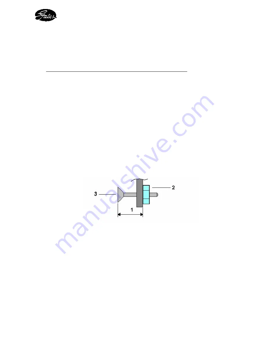
4 -   Calibrate the machine using the M6 screw (Fig. 5 / 3) positioned on the strip itself 

as follows:  


-  Measure the dimension (Fig. 5 / 1) of the screw head relative to the strip 


Figure 5 : stop strip 


-   Release the locknut (Fig. 5 / 2) 


-   Adjust screw (Fig. 5 / 3) by screwing (clockwise) to reduce the crimping  


diameter or unscrewing (anti-clockwise) to increase the crimping diameter. 


Caution

: One turn of the screw or a 1mm change in the dimension  


(Fig. 5 / 1) alters the crimping diameter by 0.65 mm 


5 -   Tighten the locknut (Fig. 5 / 2) 


6 -   Replace the stop strip at the back using the two M6 screws. 


-   Crimp another standard calibration shell (-08 MegaCrimp shell) and check the crimping 

diameter obtained. 

-      Recalibrate  the  machine  as  described  above if the crimping diameter obtained is still 

incorrect. 


Содержание MC2000

Страница 1: ...MC2000 OPERATING AND CALIBRATION INSTRUCTIONS...

Страница 2: ...INSTRUCTIONS 8 3 1 SAFETY 8 3 2 UNPACKING INSTALLATION 8 3 3 COMMISSIONING OPERATION 10 3 4 CALIBRATION 11 3 5 POSITION AND FITTING OF THE DIES 12 4 SERVICING AND MAINTENANCE 13 4 1 MAINTENANCE 13 4...

Страница 3: ...MITY The undersigned Company GATES hereby declares that the new equipment referred to hereafter as MC2000 Serial N conforms with the GATES Specification and with the Hygiene and Safety at Work Regulat...

Страница 4: ...ic Pressure 800 bar Dimensions H 310 x W 300 x L 430 mm Weight 41 Kg Crimping Capacity braided hoses from 3 16 to 1 1 4 spiral hoses 1 4 to 1 non skive 1 1 4 skived Pump Manual two speed Oil Tank 0 5...

Страница 5: ...hydraulic power required to move the dies during the crimping process Its characteristics are specially designed to provide the best compromise between available power die movement speed and ease of...

Страница 6: ...upling to be crimped onto the flexible hose It comprises the following elements see figure 2 crimping head body 6 sets of dies 7 a hollow piston moved by the oil pressure 8 eight return springs 5 a cr...

Страница 7: ...ies of thermal body and surface treatments so that they can resist the large loads and wear through friction is prevented Precise guiding is ensured by means of two Teflon Bronze bearers on the piston...

Страница 8: ...he packaging is not damaged when opening it so that it can be stored Lift the box cover then remove the screws positioned at the bottom of the packaging uprights remove the uprights from the box The c...

Страница 9: ...MC2000 USER GUIDE 9 Figure 4 Identification diagram...

Страница 10: ...to check the battery 6 is not flat and that the indicator light 7 works correctly Place the hose together with its coupling inside the crimping head 8 whilst respecting the position of the coupling i...

Страница 11: ...eter and the calibration diameter of 26 0 mm 2 Open the crimping head to its maximum 3 Unscrew the two M6 screws which hold the stop strip on the back of the piston Fig 2 2 then remove the strip Fig 2...

Страница 12: ...S In order to crimp GATES couplings correctly onto GATES hoses it is necessary to adhere to the installation positions of the dies and to the crimping positions below or Fig 5 Crimping positions and i...

Страница 13: ...ybdenum bisulfide this product is provided with the machine and is available from GATES 7482 19957 Lubricate after every 100 crimping operations as indicated below Procedure Lift the back of the die h...

Страница 14: ...HE BATTERY The end of crimping indicator light operates by way of a type 6LR 61 9 Volt battery Procedure Using the lubrication tool apply slight pressure onto the battery casing tray Pull the tray to...

Страница 15: ...g 2 Pge 6 MC2000 9088 Anti extrusion bush D 185 7482 19839 1 Item 16 Fig 2 Pge 6 MC2000 9085 O ring D 164 45 x 5 33 7482 19840 1 Item 15 Fig 2 Pge 6 MC2000 9086 O ring D 139 07 x 5 33 7482 19841 1 Ite...

Страница 16: ...r the warranty has been expressly or implicitly broken This guarantee replaces all other guarantee including implicit guarantees Every effort has been made to provide exact and exhaustive information...

Отзывы: