


www.gastron.com
24
_
25
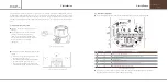
7. System Mode
7. System Mode
GTD-3000TxW
Instruction Manual
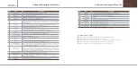
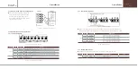
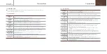
7.2. CALIBRATION MODE
7.2.1. Zero Calibration
PASSWORD
[**]
- Contacting "FUNC" key with the Magnet-bar for 2 s or longer in Measuring Mode enters Password
-
mode.
- After setting Password using "↑" or "↓" key, contact "FUNC" key.
CALIBRATION
MODE
- Contact "↑" or "↓" key to select "Calibration Mode".
- Contact "FUNC" key when "CALIBRATION MODE" is displayed to enter Calibration Mode.
- Contact "RESET" key to return to Measuring Mode.
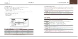
CALIBRATION
[ZERO]
- When "CALIBRATION MODE" is displayed, contacting "FUNC" key selects Zero Calibration.
- Contact "↑" or "↓" key to achieve [ZERO] then contact "FUNC" key to enter Zero Calibration.
ZERO CALIBRATION
[YES]
- Contact "↑" or "↓" key to achieve [YES] then contact "FUNC" key to perform Zero Calibration.
ZERO GAS
[ 0]
- Using a calibration tool, inject clean air or 100% nitrogen into the sensor at a flow rate of 500 mL/min
-
for 1 min. Contact "FUNC" key when measurement is stabilized to automatically perform Zero Calibration.
ZERO PROCESSING
SUCCESS >>>>
- When zero calibration is successful, "ZERO SUCCESS" is displayed for 2 sec on LCD display then it
-
changes to "CALIBRATION DATA" Mode.
- When zero calibration is not successful, "ZERO FAIL" is displayed for 2 sec and it changes to
-
"CALIBRATION DATA" Mode.
- ZERO FAIL occurs when sensor input value exceeds 70% of total ADC input range.
ZERO PROCESSING
FAIL >>>>
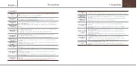
CALIBRATION DATA
[ 0]
- It is a mode to display measurement after calibration and checks whether calibration is successful after
-
performing auto calibration.
- When it failed, it displays "FAIL" and the current measurement in 1 sec interval.
- Contact "RESET" key to return to "Calibration mode".
■ Due to characteristics of the gas detector, minimum 30 min of stabilization time is required and maintenance
condition may change depending on site condition.
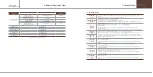
7.2.2. Span Calibration
CALIBRATION
MODE
- Contact "↑" or "↓" key to select "Calibration Mode".
- Contact "FUNC" key when "CALIBRATION MODE" is displayed to enter Calibration Mode.
- Contact "RESET" key to return to Measuring Mode.
CALIBRATION
[SPAN]
- Contact "↑" or "↓" key to achieve [SPAN] then contact "FUNC" key to enter Span Calibration mode.
SPAN CALIBRATION
[YES]
- Contact "↑" or "↓" key to achieve [YES] then contact "FUNC" key to perform Span Calibration.
SPAN GAS VALUE
[ O ]
- Using a calibration tool, inject the standard gas to the sensor at a flow rate of 500 mL/min for 90 sec.
-
After the measurement is stabilized, contact "FUNC" key to enter the next mode.
- When Hold function in Maintenance Mode is on, the current maximum SPAN gas value is held and
-
displayed in the first row.
- The current measurement is displayed in the second row.
[ 0]
< O ]
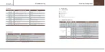
SPAN SET VALUE
[ 5O ]
- It is a mode to set standard gas value. When there is no "Fail" message, contact "↑" or "↓" key to set a
-
value.
- When the inject standard gas value is abnormal, it displays Fail message. Fail message is as follows.
-
Fail message and span set value are displayed alternatively.
-
① "LOW FAIL" occurs when the difference between injected gas value and zero calibration value is
-
below 1%.
-
② "HIGH FAIL" occurs when injected gas value is above 95% of total ADC input range.
- "RING FAIL" occurs when injected gas value runs in the current set span value, it exceeds 95% of ADC
-
input range. The above FAIL messages are automatically released if the status is normal after adjusting
-
SPAN value.
CALIBRATION DATA
CALIBRATION DATA
CAL HIGH ERROR
SPAN PROCESSING
SUCCESS >>>>
- After completing the standard gas value setting, contacting "FUNC" key automatically runs Span
-
Calibration. When it succeeds, "SPAN PROCESSING SUCCESS" is displayed on LCD display for 2 sec
-
then it changes to "CALIBRATION DATA" Mode.
- When span calibration is not successful, "SPAN PROCESSING FAIL" is displayed for 2 sec and it
-
changes to "Calibration Data Mode".
SPAN PROCESSING
FAIL >>>>
CALIBRATION DATA
[ 0]
- It is a mode to display measurement after calibration and checks whether calibration is successful after
-
performing auto calibration.
- Contact "RESET" key to return to "Calibration mode".


