background image

5

GENERAL ASSEMBLY

Assembly will require 2 people due to the Spit
Roaster size.

Connecting & Disconnecting 

to Gas Source

Familiarise yourself with the general information and
safety guidelines located at the front of this manual.

Check

1. Gas cylinder is

filled.

A sloshing sound will be

heard when shaken.

2. The burner control is in the ‘OFF’ position

Connecting

1. Ensure cylinder valve is in its full off position.
2. Check for any damage to either the cylinder

connection or the hose. NEVER attempt to use
damaged equipment.

3. When connecting the hose to the cylinder tighten

the nut to a positive stop by hand or spanner.

4. Open cylinder valve fully. If a leak can be heard

at either end of the hose turn cylinder off and
tighten joint. Wait 5 minutes before re-testing
and use a soapy water solution to check the
joint. If bubbles appear the connection will need
to be re-tightened.

Disconnecting

1. Ensure the burner control is in the

‘OFF’ position.

2. Ensure gas cylinder is in the full off position.
3. Detach the hose from cylinder.

LIGHTING PROCEDURE

Burner Operation 

& Ignition System Check

1. With cylinder valve in OFF position press the

electronic igniter button. Check for sparking to
the burners.

2. Lift hood, remove the 4 stainless steel trays,

leave hood open until both burners are fully lit.

3. If spark is not evident at the burner ignition

point, check that the ignition lead is

firmly

attached to the control and sparker tip.

4. With sparking established, turn cylinder valve

ON. Push and turn a control knob on either side
of the ignitor to HIGH and press the ignitor
button.

5. If burner fails to light after several attempts

turn off the gas supply at cylinder and inspect
for any obstructions to the gas

flo

w.

6. Both burners will need to be lit following steps

1-5.

If re–ignition is necessary while the gas spit
roaster is still hot, you must wait for a minimum of
5 minutes before commencing to re–ignite
(this allows accumulated gas fumes to clear).

After Use

Turn the gas cylinder valve off and wait for the

flame

to go out. Then turn the appliance control

valve off.

IMPORTANT

• Remove all packing and transit protection

before assembly.

CAUTION:

Ensure no packing material is

left in spit roaster before lighting. Remove
all plastic protection, usually blue

film

before

assembly and use.

• Before connecting and disconnecting spit

roaster to gas source, make sure burner
controls are in ‘OFF’ position.

CAUTION:

When the spit roaster is not in use,

the gas must be turned off at the cylinder.

• Check that the seals between the appliance

and the gas cylinder are in place and in good
condition before connecting the gas cylinder.

• Do not use this appliance if it has damaged or

worn seals.

• The appliance control knob must be in the ‘OFF’

position before opening the cylinder valve.

• If for some reason, ignitor fails to produce a

spark at the electrode, spit roaster can be lit
by a long spit roaster match. With hood open
use a lighted match from top. Push and turn a
control knob to HIGH. Light the other burner
in the same way.

• Check performance of burner prior to installing

spit roaster rack.

• Do not smoke when attempting to

ignite spit roaster.

• Never use volcanic rock, heat beads

or other material.

• Always use protective gloves when handling

hot components.

Содержание GSB300

Страница 1: ...ie motor rated at 70kg one piece stainless steel shaft two prongs neck brace front leg brace rear leg brace and rotisserie baskets Gasmate is a registered trademark of Sitro Group Australia Pty Ltd www gasmate com au Aber Hamilton N Z www gasmate co nz FEATURES Electronic ignition for easy lighting Complete with hose regulator Use with LPG For outdoor use only AGA certified ...

Страница 2: ... 75kPA is supplied for connection to the LPG cylinder The gas regulator and hose assembly supplied with the spit roaster must be used Replacement gas regulators and hose assemblies must be those specified by the spit roaster manufacturer When connecting the hose and regulator assembly to the gas cylinder take care to avoid unnecessary twisting of the flexible hose After the assembly has been secured...

Страница 3: ...t roaster parts as you proceed with assembly Contact your supplier for assistance regarding replacement of any damaged or missing parts Do not assemble or operate a spit roaster that appears damaged Spit roasters for use with gas cylinders are labelled LPG Check labelling at the gas connection on your spit roaster Protect Children Keep children away from spit roaster during use and until spit roas...

Страница 4: ... causing death or serious injury may occur Do not store a spare gas cylinder under or near this spit roaster Never fill the cylinder beyond 85 full This spit roaster is only to be used and stored outdoors If you smell gas 1 Shut off gas to the spit roaster at its source if possible 2 Extinguish any open flame 3 Open hood 4 If odour continues immediately call your gas supplier or fire department Do no...

Страница 5: ...de of the ignitor to HIGH and press the ignitor button 5 If burner fails to light after several attempts turn off the gas supply at cylinder and inspect for any obstructions to the gas flow 6 Both burners will need to be lit following steps 1 5 If re ignition is necessary while the gas spit roaster is still hot you must wait for a minimum of 5 minutes before commencing to re ignite this allows accu...

Страница 6: ...ot be used until serviced or repaired BURNER OPERATION IGNITION SYSTEM CHECK OPERATING PROCEDURE Burn off Before cooking for the first time operate the spit roaster for about 15 minutes with the hood closed and the gas turned on HIGH This will heat clean the internal parts and dissipate odour from the finish Preheating It is necessary to preheat the spit roaster for at least 5 minutes before cooking...

Страница 7: ... manufacturer may cause injuries Extreme caution must be used when moving an appliance containing hot oil or other hot liquids DO NOT use this appliance for anything other than intended use Only connect this rotisserie to 240V AC power DO NOT place on or near a hot gas or electric burner or in a heated spit roaster Check for damaged parts before operating this rotisserie Do not touch any hot compo...

Страница 8: ...Rinse with water and alow to dry Cleaning the burner assembly Turn the gas OFF at the control knob and disconnect the cylinder Clean the burner with a soft brush or blow clean with compressed air and wipe with a cloth Clean any clogged ports with a pipe cleaner or stiff wire such as an opened paper clip Flash Back Spiders and small insects occasionally spin webs or make nests in the burner tubes d...

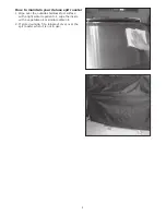
Страница 9: ...t roaster 1 Wipe over the outside stainless steel surface with a light water repellent oil wipe the inside with a vegetable oil or similar edible oil 2 If stored outside fit a rainproof cover over the spit roaster when it is not in use ...

Страница 10: ...10 EXPLODED DIAGRAM ...

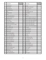
Страница 11: ...ie shaft support back 1 15 Burner main 2 51 Rotisserie shaft restrict piece support 2 16 Burner flame tamer 2 52 M10 screw 2 17 Electronic wire set 2 53 M10 Butterfly nut 2 18 Burner nozzle 2 54 Roller fixed front 1 19 Shield board 2 55 Roller fixed back 1 20 Thermocouple support 2 56 Thermocouple 2 21 Body inner anelleft right 2 57 Tracheal 2 22 Body inner panel support 2 58 Gas valve 1 23 Body panel...

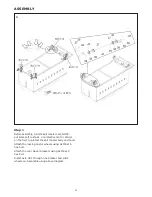
Страница 12: ...hions or protective mat or similar on the floor to protect the spit roaster body and hood Attach the locking castor wheels using 8x M8x15 hex bolt Attach the rear wheel brackets using 8x M8x15 hex bolt Insert axle 41 through one bracket and slide wheels on Assemble using above diagram 1 ...

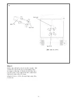
Страница 13: ...its support first loosen and remove the four pre assembly M5 x 8 screws on the base of the motor Ref 69 then put the motor on its support Ref 70 install and tighten the same M5 x 8 screws Attach ref 69 70 to the spit body using M6 x 12 screws 2 ...

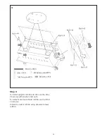
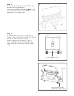
Страница 14: ... Step 3 To install uprights ref 49 and 50 use the M6 x 35 screws with washers and nuts To install motor heat shield ref 65 use the M5 X 10 screws Install the rollers ref 44 using shoulder screws ref 55 3 ...

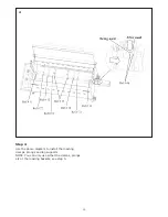
Страница 15: ...15 Step 4 Use the above diagram to install the roasting clamps prongs and leg supports NOTE You can only use either the clamps prongs etc or the roasting baskets see step 5 4 ...

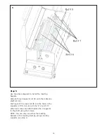
Страница 16: ...tisserie shaft ref 10 Push each of the racks ref 6 into the holes in the supports ref 8 Secure with the R clip ref 7 When all 4 racks are fitted tighten the 2 supports to the shaft using the screws NOTE You can only use either the roasting baskets or the roasting clamps prongs and leg supports see step 4 5 ...

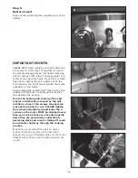
Страница 17: ...paced along the cooking length Step 7 To fit the fat tray slide the tray ref 5 into the grooves under the spit roaster on the same end as the motor Push in until fully located NOTE If emptying or fitting fat tray during cooking extreme caution should be taken and direct contact by hand should be avoided at all times Fat Tray slides in here Fat tray slides in here at bottom or spit roaster Ref 5 ...

Страница 18: ...nting Due to the heating and cooling of the spit roaster and vibrations caused by the spit rotations some of the screws may become loose during transit or use PLEASE tighten the screws periodically in particular the 4 screws on the motor MUST be checked every time you cook as these are mounted upside down they are particularly vulnerable to becoming slack and a motor falling off could be a disaste...

Страница 19: ...ed and balanced Unboned Meat For meats which are unboned it is best to secure the rotisserie skewer diagonally through the meaty sections When to Use Foil If protuding bones or wings brown too quickly cover with pieces of foil COOKING TIMES This will vary according to the type and weight of food you are cooking Insert a meat thermometer into the centre of the meat avoiding bone which will provide ...

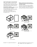
Страница 20: ...vel and no overhead cover see Example 1 Within a partial enclosure that includes an overhead cover and no more than two walls see Example 2 3 Within a partial enclosure that includes an overhead cover and more than two walls the following will apply at least 25 of the total wall area is completely open and at least 30 of the remaining wall area is open and unrestricted see Example 4 5 In the case ...

Отзывы: