background image

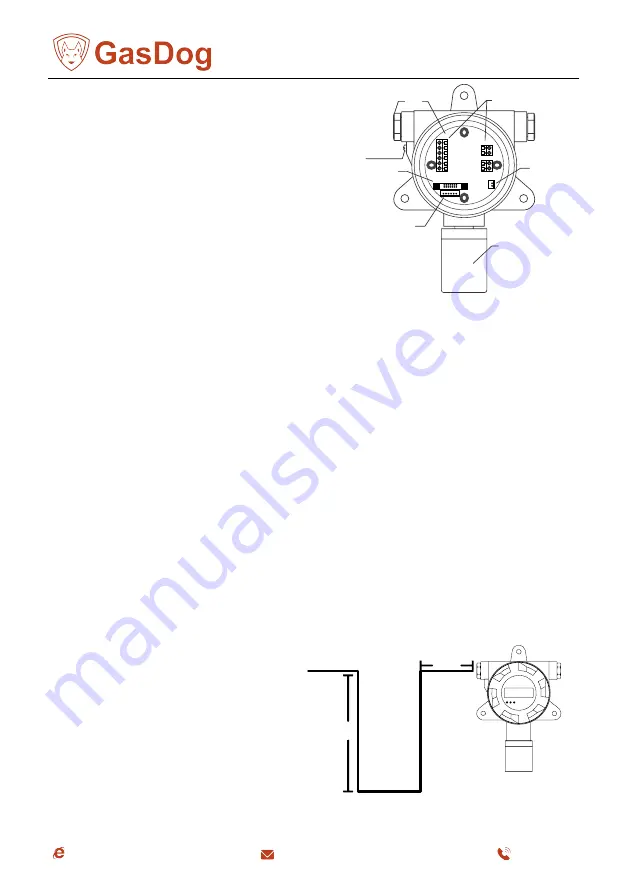
2 Structure diagram

1,Power supply and Signal line entrance and exit 

2,Circuit board

3,Terminals

4,Sound and light alarm interface

5,Sensor head

6,Sensor head interface

7,Connect the claw socket to the mainboard

3  Installation method

 Select the installation location

The installation position is very important to achieve the best detection effect.

When determining the location, it is necessary to comprehensively consider the following factors: 

such as the density of the gas leak point, the specific gravity of the gas to be measured, the influence of 

the surrounding buildings, the age of the production equipment, the wind direction and the weather 

conditions all year round, etc. The location of doors and windows should also be considered indoors.

The following suggestions are for users' reference:

A. Appropriate distance should be maintained between the instrument and the possible leakage point of 

the gas to be tested. If it is too close, the reaction speed will be very fast, but if the leakage is frequent, it will 

cause too many alarms, or the long-term alarm state will make people paralyzed; if it is too far, the reaction 

speed will be too slow, or even no response.

B. The instrument should be installed in the downwind direction of the leakage point.

C. When installing indoors, if the leakage source is outdoors, the instrument should be installed at 

the air inlet.

D. The installation height should be determined according to the specific gravity of the measured gas and 

air.

E. The number of instruments should be selected according to the possible leakage points of the gas to 

be measured, the frequency of personnel appearance and the residence time, so as to achieve the best 

detection effect.

F. If the equipment is outdated, it can be considered to increase the measured points.

G. The instrument should be prevented from being radiated by a high temperature heat source. Too 

high or too low temperature will affect the use effect and lifetime of the sensors.

≥30CM

≤2CM

Cable

Figure H

IR AL AH

8.8.8.8

H. The instrument should be protected 

from damp and rainwater inflow, which will 

affect the internal circuit board. 

The wiring recommendations are shown 

in the diagram below.

Ground 

connection port

5

6

1

2

3

4

7

4

www.gasdog.com

[email protected]

+86 773-280-9002

Содержание GD300 Series

Страница 1: ...Online Fixed Gas Detector GD300 XX Instruction Manual Notice to Reader Please read this instruction manual before using the detector 1 www gasdog com sales gasdog com 86 773 280 9002...

Страница 2: ...ery 3 6 months the explosion proof disc of the sensor should be cleaned regularly purging with low pressure compressed air according to the applicable scene otherwise dust and impurities will block th...

Страница 3: ...re operation 2 Structure diagram 3 Installation method 4 Wiring Instructions 5 Calibration method 6 Remote controller operation 7 Common faults and repairs 8 Instrument con guration 9 Appendix 3 www g...

Страница 4: ...many alarms or the long term alarm state will make people paralyzed if it is too far the reaction speed will be too slow or even no response B The instrument should be installed in the downwind direc...

Страница 5: ...ype The installation thread size of the instrument is M45 P2 0 During the installation process hold the detector with both hands so that the sensor is parallel to the installation thread align the scr...

Страница 6: ...rance and installation hole map 118 00 8 00 140 00 8 00 8 00 102 30 206 00 89 00 Apperance and installation hole map of gas detector with alarm light 8 00 179 00 102 00 8 00 8 00 118 00 206 00 89 00 6...

Страница 7: ...mula The maximum current of combustible gas detector is 250mA and the maximum loop resistance is 48 The maximum current of the toxic gas detector is 100mA and the maximum loop resistance is 120 The ca...

Страница 8: ...the load resistance which includes the output resistance of the control system controller DCS or PLC and the internal resistance of the cable Cable distance m 100 200 500 1000 The maximum allowable n...

Страница 9: ...needs to open the instrument shell and connect wires to the inside terminals The following gure is the description of each terminal Warning The wiring work must be performed by professionals otherwis...

Страница 10: ...the alarm settings of the detector and the panel are adjusted to the factory default values and the user can adjust it through the remote controller according to the situation Zero calibration Make su...

Страница 11: ...zero calibration is successful it will automatically return to the detection interface IR ALAH Span calibration Connect the calibration gas cylinder of known concentration to the calibration cap Opti...

Страница 12: ...i ed by the and keys to make the value consistent with the calibration gas concentration Press the OK key to display PASS brie y IR ALAH IR ALAH IR ALAH IR ALAH IR ALAH IR ALAH 2 Press the key to disp...

Страница 13: ...ting menu press the OK key to enter the modi cation press the and keys to modify the instrument address code and press the OK key to save after the modi cation is completed Press the BACK key to cance...

Страница 14: ...value Calibration after stable reading in clean environment F 05 4MA current trimming C 04 4mA output modi able C 08 8mA output cannot be modi ed C 12 12mA output cannot be modi ed C 16 16mA output c...

Страница 15: ...ot enough warm up time Sensor failure Circuit failure Send back for repair recalibrate Reset the detector range Replace the sensor recalibrate Reset the detector range Replace the sensor Power on and...

Страница 16: ...tively These two signal output modes are also di erent when wiring A 4 20mA current signal output connection mode must be grounded together B RS485 digital signal output connection mode 1 can be indep...

Страница 17: ...C RS485 digital signal output connection mode 2 can be independently grounded RS485B RS485A GND PC software RS485 to USB 1 2 N 24V DC GND 17 www gasdog com sales gasdog com 86 773 280 9002...

Отзывы: