


Electronic
Head
Assembly
03/07/03
3-7
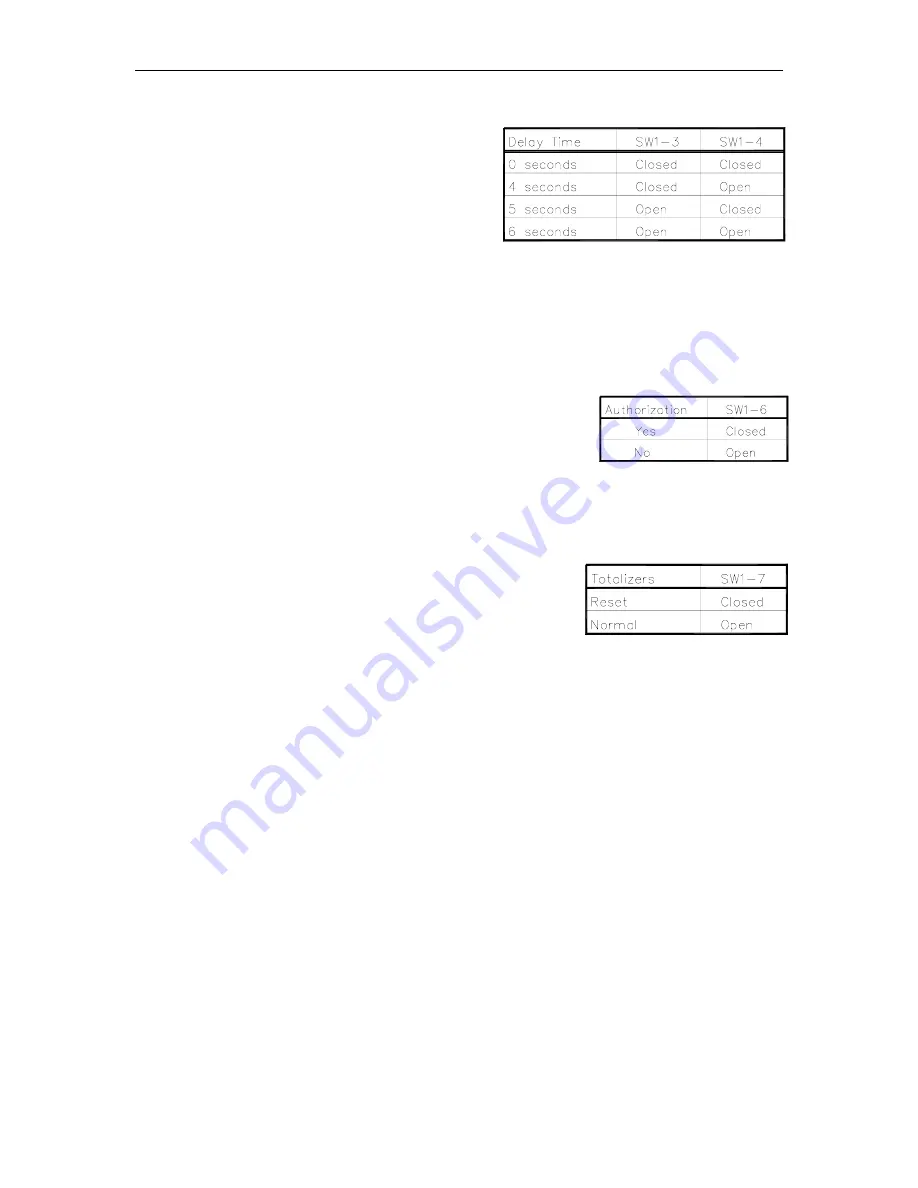
SW1-3, SW1-4 Delay Time
These two switches set the delay time used by
leak detectors in submersible pump applications.
The delay time is the period between activation of
the submersible pump and activation of the slow
flow valve. This time should be set according to
the type of leak detector installed on the
submersible pump to allow a normal leak test for
each transaction. The delay time should be set to
zero seconds for suction pumps.
SW1-5
Not used.
SW1-6 Authorization
This switch allows activation or non-activation of the unit through
an external source (fuel management system). When closed, a
115/230 VAC signal must be present on the Control Feed (pump
motor or subm) line for pump activation to occur (required setting
for Series 1000). When open, the 9800A ignores the Control
Feed line (required setting for CFN System or no fuel
management system).
SW1-7 Totalizers
This switch should be set to open for normal operation. When
closed, this switch enables the reset of the electronic totalizers.
SW1-8
Not used.
Содержание 9800A Series
Страница 8: ......
Страница 11: ...Chassis Wiring 03 07 03 2 3 115VAC 60 CYCLE PUMP WIRING...
Страница 12: ...GASBOY Series 9800A 2 4 03 07 03 115VAC 60 CYCLE DISPENSER WIRING...
Страница 13: ...Chassis Wiring 03 07 03 2 5 230VAC 50 CYCLE PUMP WIRING...
Страница 14: ...GASBOY Series 9800A 2 6 03 07 03 230VAC 50 CYCLE DISPENSER WIRING...
Страница 15: ...Chassis Wiring 03 07 03 2 7 115VAC 60 CYCLE FRONT LOAD OPTION PUMP WIRING...
Страница 16: ...GASBOY Series 9800A 2 8 03 07 03 115VAC 60 CYCLE FRONT LOAD OPTION DISPENSER WIRING...
Страница 17: ...Chassis Wiring 03 07 03 2 9 230VAC 50 CYCLE FRONT LOAD OPTION PUMP WIRING...
Страница 18: ...GASBOY Series 9800A 2 10 03 07 03 230VAC 50 CYCLE FRONT LOAD OPTION DISPENSER WIRING...
Страница 19: ...Chassis Wiring 03 07 03 2 11...
Страница 20: ......
Страница 39: ...Electronic Head Assembly 03 07 03 3 19 Connectors Relay Drive Pump Motor Power...
Страница 60: ......
Страница 63: ...Replacement Instructions 03 07 03 5 3 ON POWER OFF E S F U S U 1 AMP SB E F MICRO POWER LIGHTS HEATER LOOSEN...
Страница 65: ...Replacement Instructions 03 07 03 5 5...
Страница 72: ...GASBOY Series 9800A 5 12 03 07 03...
Страница 75: ......
Страница 76: ...APPENDIX PARTS LIST...
Страница 77: ......


