background image

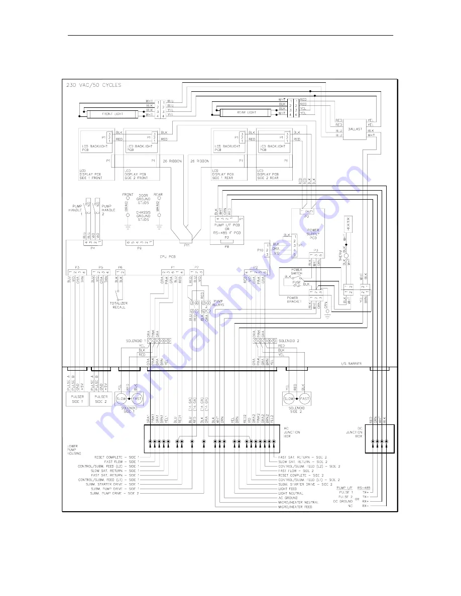
GASBOY Series 9800A 


2-6 

03/07/03 

230VAC/50 

CYCLE 

DISPENSER 

WIRING 


Содержание 9800A Series

Страница 1: ...disclosure shall be made without permission of Gasboy International LLC Gasboy International LLC believes that the information in this document is accurate and reliable However we assume no responsibi...

Страница 2: ...pumping fuel or additives into aircraft DO NOT use commercial pumps for direct fueling of aircraft without filters and separators necessary to ensure product purity DO NOT use where sanitary design i...

Страница 3: ...cle Front Load Option Dispenser Wiring 2 10 Section 3 ELECTRONIC HEAD ASSEMBLY Overall Layout 3 1 CPU PCB 3 2 Connectors 3 3 Jumpers 3 5 LED Indicators 3 6 Test Points 3 6 SW Switches 3 6 Address Swit...

Страница 4: ...Parts List 1 9800A Single Assembly Front View 2 9800A Single Assembly Side View 4 9800A Twin Assembly Front View 6 9800A Twin Assembly Side View 8 9840A Assembly Front View 10 9840A Assembly Side Vie...

Страница 5: ...853ATW1M Motor 73 9853ATW2 9853ATW1M Motor 380V 74 Nozzle Boot Front Load Option 75 9840 Pumping Unit Assembly 76 9850A Pump and Platform Assembly 77 9852A 9853A Pumping Unit Assembly 78 9853AHC Pumpi...

Страница 6: ...Canada ATC 097273 104 9852A Filter Discharge 097359 Canada ATC 097338 104 9852ATW2 Discharge Assembly 097209 Canada ATC 097417 105 9852ATW2 Filter Discharge Assembly 097208 Canada ATC 097417 105 9853...

Страница 7: ...o be taken The probable causes and checks for each problem are presented in logical sequence allowing you to rule out one set of symptoms before going on to the next Thus following the procedures as l...

Страница 8: ......

Страница 9: ...power supplied on the Control Pump Motor or Control Submersible Feed lines Control Submersible Feed Hot side of the power used to authorize the control line to the dispensing unit Provides power to sl...

Страница 10: ...ps DC at voltages up to 24 VDC The pulse rate can be configured by a sealable DIP switch for rates of 1 10 100 250 500 or 1000 pulses per unit gallons or 1 10 100 or 250 pulses per unit liters This ou...

Страница 11: ...Chassis Wiring 03 07 03 2 3 115VAC 60 CYCLE PUMP WIRING...

Страница 12: ...GASBOY Series 9800A 2 4 03 07 03 115VAC 60 CYCLE DISPENSER WIRING...

Страница 13: ...Chassis Wiring 03 07 03 2 5 230VAC 50 CYCLE PUMP WIRING...

Страница 14: ...GASBOY Series 9800A 2 6 03 07 03 230VAC 50 CYCLE DISPENSER WIRING...

Страница 15: ...Chassis Wiring 03 07 03 2 7 115VAC 60 CYCLE FRONT LOAD OPTION PUMP WIRING...

Страница 16: ...GASBOY Series 9800A 2 8 03 07 03 115VAC 60 CYCLE FRONT LOAD OPTION DISPENSER WIRING...

Страница 17: ...Chassis Wiring 03 07 03 2 9 230VAC 50 CYCLE FRONT LOAD OPTION PUMP WIRING...

Страница 18: ...GASBOY Series 9800A 2 10 03 07 03 230VAC 50 CYCLE FRONT LOAD OPTION DISPENSER WIRING...

Страница 19: ...Chassis Wiring 03 07 03 2 11...

Страница 20: ......

Страница 21: ...03 07 03 3 1 Section 3 ELECTRONIC HEAD ASSEMBLY OVERALL LAYOUT Use this drawing as a guide to identifying the components in a 9800A electronic head assembly...

Страница 22: ...ansaction and totalizer data retention during power failures controls the data sent to the display PCB s controls the relays for each pump side monitors the dual channel pulser inputs for each pump si...

Страница 23: ...eds the SF FF and SUBM relays The SF and FF outputs can directly power the solenoid valves The SUBM output can power a customer supplied submersible starter relay The starter relay s coil current must...

Страница 24: ...izer Switch The electronic totalizer switch connects to P6 P7 Suction Pump Submersible Pump Relay Drives The suction pump submersible pump optional relays connect to P7 P8 RS 485 Pump Interface The op...

Страница 25: ...Option P10 Power Supply Input P11 LCD Display Interface Jumpers Jumper K1 is set according to the size of the RAM IC in socket U19 The 9800A CPU PCB can accommodate two sizes of battery backed RAM 2K...

Страница 26: ...hange their settings if necessary Switch settings should be changed with the power switch OFF The new settings are read by the CPU PCB when the power is turned ON again SW1 SW1 1 Baud Rate This switch...

Страница 27: ...time should be set to zero seconds for suction pumps SW1 5 Not used SW1 6 Authorization This switch allows activation or non activation of the unit through an external source fuel management system Wh...

Страница 28: ...Switches When the 9800A is connected to external control equipment other than a GASBOY CFN system standalone the pulser signals are sent out via the 9800A Pump I F PCB The pulse rate required by the m...

Страница 29: ...bly 03 07 03 3 9 LCD DISPLAY PCB C01373 The LCD Display PCB contains the quantity display viewed by the user This PCB displays the quantity per sale totalizer data and diagnostic information Connector...

Страница 30: ...CB can be configured to display whole units tenths hundredths or thousandths Presently all domestic 9800A s except 9850A are shipped displaying thousandths of a gallon all international 9800A s are sh...

Страница 31: ...GHT PCB C06372 The backlight PCB illuminates the LCD display for night viewing This PCB attaches to the 9800A LCD display PCB combines long life super bright LED s with a reflector for increased surfa...

Страница 32: ...communicate on the GASBOY RS 485 loop This PCB provides protection against noise and damaging voltage transients that may be induced onto the RS 485 lines contains diagnostic LED s to monitor operatio...

Страница 33: ...Electronic Head Assembly 03 07 03 3 13 LED Indicators LED indicators are provided to allow you to monitor the RS 485 communication lines...

Страница 34: ...nal monitoring equipment that does not support the GASBOY RS 485 electronic pump loop This PCB provides a pulser signal for each pump side up to 100 mA at 24 VDC The current and voltage are determined...

Страница 35: ...Electronic Head Assembly 03 07 03 3 15 P2 CPU PCB Interface LED Indicators LED indicators are provided to allow you to monitor the pulser output lines...

Страница 36: ...VAC C06489 The power supply PCB provides 5VDC logic power and 7 5VDC LED backlight power diagnostic LED s to monitor DC voltages a signal to warn the microprocessor of an impending power failure recha...

Страница 37: ...3 07 03 3 17 Connectors P1 CPU Power Output P2 Backlight Power Output P3 AC Input LED Indicators LED indicators are provided to allow you to monitor the DC voltages Test Points Test points are provide...

Страница 38: ...The pump relays are always used for suction pumps and may be used for submersible pumps up to and including 1 1 2 HP at 230 VAC These relays control the motor that drives the suction or submersible pu...

Страница 39: ...Electronic Head Assembly 03 07 03 3 19 Connectors Relay Drive Pump Motor Power...

Страница 40: ...GASBOY Series 9800A 3 20 03 07 03 BALLAST ASSEMBLY 115 VAC C06473 230 VAC C06476 The ballast assembly provides power for the fluorescent lights Connectors Front and Rear Lamps Input Power...

Страница 41: ...03 3 21 FLUORESCENT LAMP ASSEMBLY C06398 FLUORESCENT LAMP 033412 The fluorescent lamp assemblies illuminate the brand panels OR FLUORESCENT LAMP ASSEMBLY C07117 FLUORESCENT LAMP 033412 Connector Inpu...

Страница 42: ...TAT CABLE ASSEMBLY 115 VAC C06450 230 VAC C06490 The heater assembly is used to warm the power supply battery in extreme temperatures and conditions It contains a 25W heater strip contains a thermosta...

Страница 43: ...CKET ASSEMBLY C06436 The Power Bracket Assembly contains the switch fuse and AC connectors Connectors Micro Power Input Connects to AC power from conduit assembly Heater Power Supplies AC power to opt...

Страница 44: ...activated shows the pump s totalizer data on the sale displays A rear extension cable allows the totalizer to be activated from both sides of the unit Front Cable Rear Cable ELECTRONIC TOTALIZER ACTUA...

Страница 45: ...ures as listed should help isolate your problem A double line at the end of a problem sequence indicates the last of the checks for that problem If your unit still is not working recheck your symptoms...

Страница 46: ...wer switch is off Check the power switch Turn on if off AC power fuse is blown Check the fuse in power bracket Replace fuse if blown Blown power supply PICO fuse s or defective power supply Using a vo...

Страница 47: ...ment system and correct the problem Mode switch on CPU PCB set incorrectly Check switch SW1 2 on CPU PCB Close switch if open Turn power switch off then on after changing switch settings 9800A is runn...

Страница 48: ...3 07 03 Possible Cause Checks Corrective Action Defective CPU PCB None Replace the CPU PCB if the 9800A still will not activate NOTE Changing the pulser rate switches may require replacement of your W...

Страница 49: ...ot communicating to the GASBOY CFN System 9800A won t activate in standalone mode Verify that the 9800A works in standalone mode Close SW1 2 on the CPU PCB turn the power switch off and on then perfor...

Страница 50: ...figured correctly Make sure the pump type is 2 with no options for the Site Controller II or type 64 for the Site Controller I Incorrect switch settings on 9800A CPU PCB Verify that the SW1 switches a...

Страница 51: ...replacement of your Weights and Measures seal Replace the CPU PCB if 115 230VAC is not measured between screw terminal 1 and 3 NOTE Changing the pulser rate switches may require replacement of your W...

Страница 52: ...ween screw terminals 1 and 3 of terminal SOL1 or SOL2 Replace the CPU PCB if 5VDC is measured between ground and the blue or violet wires NOTE Changing the pulser rate switches may require replacement...

Страница 53: ...y time Leak in supply line or piping Select a longer delay time if needed Replace defective leak detector if it does not open Repair leak Shear valve tripped Try to determine cause loose mounting to i...

Страница 54: ...While dispensing fuel slowly measure between GND TP2 and pins 1 and 2 of connector P3 side 1 or P5 side 2 on the CPU PCB using an oscilloscope Replace the pulser if a 5VDC square wave is not measured...

Страница 55: ...he pulser signal to a DC voltage between 5VDC and 24VDC Call GASBOY Technical Service for assistance Defective CPU PCB Using an oscilloscope check the signal between GND TP2 and the following pins of...

Страница 56: ...talizer data Possible Cause Checks Corrective Action Pump Handles are on Check if pump handles are on Turn pump handles off if on Possible misalignment of totalizer switch and magnet Check alignment R...

Страница 57: ...tion ROM failure None Replace ROM IC U18 on CPU PCB Replace CPU PCB if replacing U18 did not fix problem STANDALONE MODE ERROR HANDLING When operating the pump dispenser in standalone mode not connect...

Страница 58: ...breaker if 115 230 VAC is not being switched Correct wiring problems if 115 230 VAC is not measured Turn on if off Replace fuse if blown Defective AC power fail circuit Using a DC voltmeter measure be...

Страница 59: ...e switch is closed the 9800 will timeout if it doesn t detect pulses for 4 minutes 15 seconds To set the 9800 to never timout open SW2 4 With the 9800A in standalone mode one or more displays flash 58...

Страница 60: ......

Страница 61: ...it should be turned off In submersible pump applications turn off power to the submersible pump and any other dispensers which use that submersible pump AC power can feed back into a shut off dispense...

Страница 62: ...anel 2 Remove the two bolts located over the tabs of the bezel assembly Lift the bezel assembly upwards and out to remove If the model includes the front load nozzle remove the nozzle boot plastic shr...

Страница 63: ...Replacement Instructions 03 07 03 5 3 ON POWER OFF E S F U S U 1 AMP SB E F MICRO POWER LIGHTS HEATER LOOSEN...

Страница 64: ...retaining hardware 4 from the platform 5 Disconnect the cables 5 from the rear door PCB s 6 Remove the hardware 6 securing one of the support brackets Be careful not to let the door fall off while re...

Страница 65: ...Replacement Instructions 03 07 03 5 5...

Страница 66: ...ndoffs 4 Remove the program IC from socket U18 3 and the memory IC from socket U19 4 of the defective CPU PCB by gently prying with a slotted screwdriver 5 Install the old program IC and memory IC int...

Страница 67: ...display PCB from standoffs 3 4 Remove the two Phillips screws 4 and washers securing the Sale Backlight PCB to the LCD Display PCB 5 Reverse Steps 1 through 4 to install the new LCD Display PCB 6 Veri...

Страница 68: ...from the Sale Backlight PCB 2 Remove the two Phillips screws 2 and washers securing the Sale Backlight PCB to the LCD Display PCB 3 Unsnap and remove the two plastic buttons 3 securing the Sale Backli...

Страница 69: ...9 REPLACING THE POWER SUPPLY PCB 1 Disconnect the cables 1 from the Power Supply PCB 2 Remove the two screws 2 from the Power Supply PCB and then unsnap PCB from standoffs 3 3 Reverse Steps 1 and 2 t...

Страница 70: ...e RS 485 or Pump I F PCB 3 Pull the RS 485 or Pump I F PCB from the CPU PCB 4 Reverse Steps 1 through 3 to install the new RS 485 or Pump I F PCB NOTE Older units may have a 5 position cable from DC c...

Страница 71: ...ply pressure to the retaining tab on one side of the LIGHTS connector 1 on the power bracket then push the connector in through bracket 3 Disconnect the lamp cable assemblies 2 from the ballast cable...

Страница 72: ...GASBOY Series 9800A 5 12 03 07 03...

Страница 73: ...to the platform on older units two nuts must be removed 7 Reverse Steps 2 through 6 to install the new ballast cable assembly Be sure to install a new tie strap or push in wire twist standoff to keep...

Страница 74: ...thermostat to the platform Push the thermostat through the bushing 3 Disconnect the HEATER connector 2 from the power bracket 4 Remove the two Phillips screws 3 and fiber washers retaining the heater...

Страница 75: ......

Страница 76: ...APPENDIX PARTS LIST...

Страница 77: ......

Отзывы: