SECTION 4
INSTRCTIONS FOR USE
4.1 BEFORE USE
WARNING!
Before starting up the machine the operator must read
and assimilate this entire manual, particularly Section 2
which deals with safety.
Furthermore, before starting work, check that the machine
is in order and that all the parts subject to wear and
deterioration are in perfect condition.
4.2 USE
The band saw has been exclusively designed and
manufactured for cutting ferrous materials with tubular,
open or filled sections.
Use of the machine for cutting other materials or for
different processing that do not comply with the uses
described in this manual, is not only to be considered
improper and prohibited, but also release the
Manufacturing Company from any responsibility, both
direct and indirect.
Before inserting the plug into the socket, ensure that the
voltage corresponds to that marked on the identification
plate (17 Fig.1).
4.3 OPERATION
·
Connect the machine plug and switch on the machine.
·
Turn the total switch (8 Fig.1). A pilot light switches (8.1
Fig.1) on to signal that the machine is energized.
·
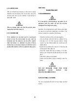
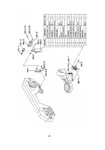
Check that the band tensioning microswitch is pressed
down, otherwise the machine will not work(1 Fig.7).
·
Raise the saw bow, ensure setting bracket is
disconnected from limit switch.
Start
1. Turn Emergency (red mushroom) (6 Fig.1).
2. Start the band saw.
·
Turning the option switch to position “handgrip
control” (7.1 Fig.1), press the button (2 Fig.1).
·
Turning the option switch to position “ main switch”
(7.1 Fig.1), press the main switch (7 Fig.1).
Stop
To stop the band saw
12
·
Push the Emergency (red mushroom) (6 Fig.1).
·
Turn the total switch (8 Fig.1) to “OFF” (or position “0”).
Fig.7
4.4 CONTROL DEVICES
The machine is equipped with the following control
devices:
1. Total switch (8 Fig,1)
The function of this switch is to power supply the machine.
When it is on, a pilot light indicates that the machine is
energized.
(3
∽
Motor only ) (“0” position: the saw blade does not
rotate; POSITION “1”: This is the position of the lowest
speed; POSITION “2”: This is the position of the fastest
speed.)
2. Emergency stop (6 Fig.1)
The machine is equipped with an emergency push button
used to stop the machine in an emergency. The stop push
button must be released before the machine is restarted
after an emergency stop.
3. Option switch (7.1 Fig.1)
The function of this switch is option circuit. (“handgrip
control” or “main switch”)
4. Main switch (7 Fig.1)
Press this switch, the band saw is running.
5. Handgrip with control push button (1 Fig.1)
The handgrip control (the operator must e present ) is
used to lift or lower the bow, in order to carry out the
cutting operation. This handgrip consists of a tube,
secured to the machine head: the handgrip control with its
push button is fitted to the end of the tube.
Press the button(2 Fig.1) to star rotating the saw blade;
release the button to stop it.
Furthermore, the handgrip is equipped with a safety
device to guard against accidental star up.
Содержание BS260
Страница 5: ...4...
Страница 6: ...5...
Страница 18: ...17...
Страница 22: ...21...
Страница 23: ...22...
Страница 24: ...23...
Страница 25: ...24...
Страница 26: ...25...
Страница 27: ...NOTES Page 27...
Страница 28: ...Distributed by Garrick Herbert Pty Ltd KIRRAWEE NSW Australia www garrickherbert com au...


