background image

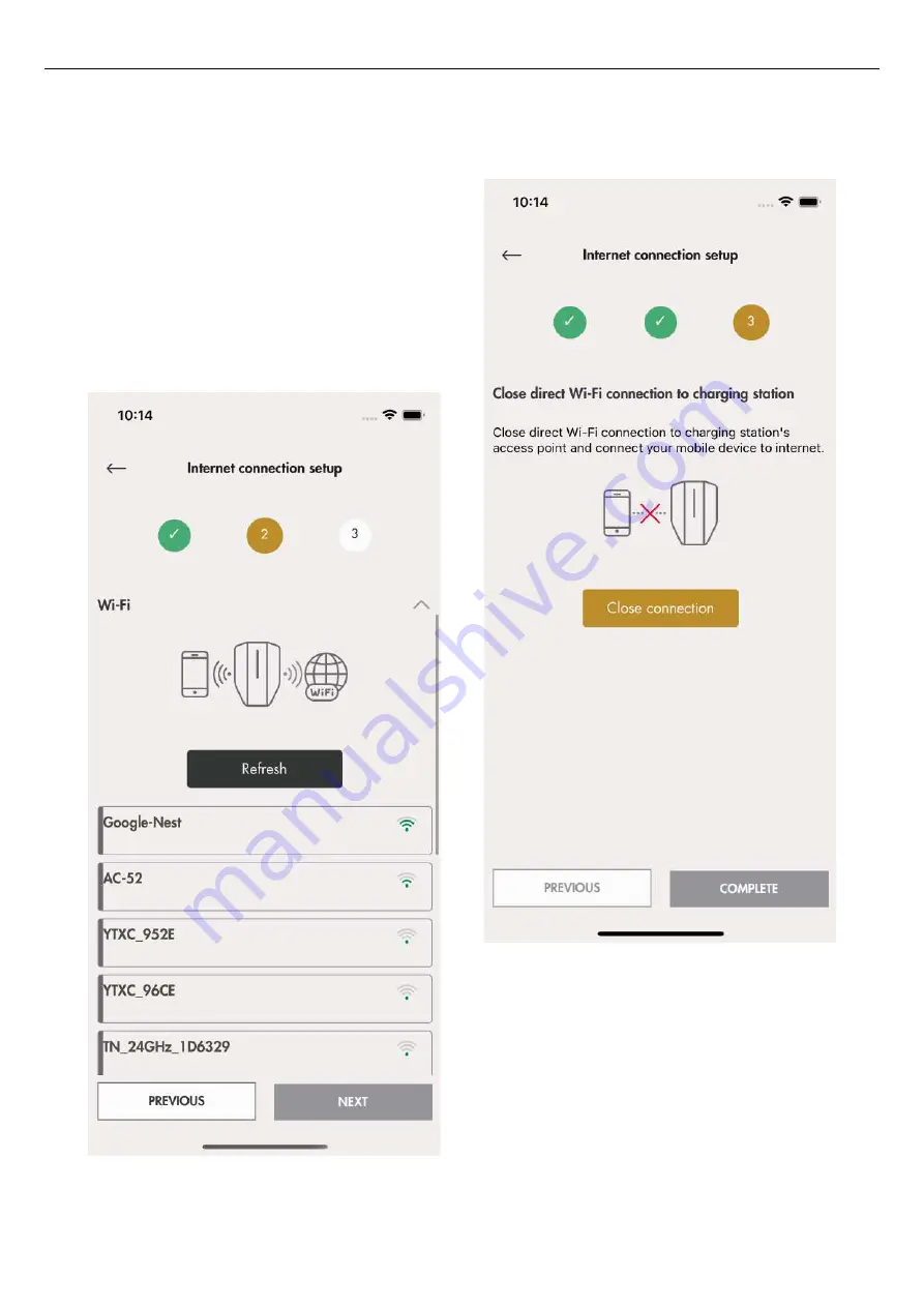
b. Choose preferred internet connection and click

Next.

If the ethernet cable is connected to the internet,

the charging unit will automatically connect

through the cable. If neither ethernet nor Wi-Fi is

available the charging unit will automatically

connect through 4 G/LTE. If the charging station

is configured as part of a connection group

trough a mesh Wi-Fi then the charging station

will automatically be connected via this mesh

Wi-Fi group.

c. The Internet icon will turn green connected to the

internet.

55

Installation

Содержание ENTITY PRO

Страница 1: ...GAROEntityProinstallationand operation GARO Entity Pro installation and operation...

Страница 2: ...2 Simple setup scenarios 22 4 10 3 Advanced setup scenarios 22 4 11 To decide the position of the charging station 23 4 12 Cable installation 23 4 12 1 To install the stickers for IT 230 V 24 4 12 2...

Страница 3: ...n light 76 5 2 To schedule charging 77 5 3 To monitor the charging process 77 5 4 To stop the charging of the electrical vehicle 77 6 Maintenance 79 6 1 To clean the charging station 79 6 2 To do a vi...

Страница 4: ......

Страница 5: ...controlled by one device either a charging station or a load interface to act as a master device Normally the Connection group also defines how the internet is connected to the units trough a master...

Страница 6: ...ner can add other owners manage access for EV drivers and EV driver groups manage charger groups and create locations organizations and EV driver groups The owner can monitor and control status of the...

Страница 7: ...UK GARO Electric Ltd Sales Customer Service Unit 16 Urban Express Park Aston Hall Road Birmingham B6 7FH 7 Introduction...

Страница 8: ......

Страница 9: ...s and regulations not to exceed charging current limitations Ventilation signal from EV is not supported This means that test of State D is not possible Adapters for charging connectors are not allowe...

Страница 10: ......

Страница 11: ...ront cover for charging units without an MID certified visible energy meter The front cover is available in several colors D Front cover for charging units with an MID certified visible energy meter T...

Страница 12: ...veral colors Installation bracket single IB The installation bracket is where the physical installation is done It contains a permanent RFID tag with the identity of the physical charging station The...

Страница 13: ...3 3 PRODUCT VARIANTS The Entity Pro charging station and separate charging unit is available in several product variants A B C D 13 Product overview...

Страница 14: ...visible energy meter The product concept can for special high volume orders be customized to with or without the features listed below Type 2 outlet or fixed cable Long fixed cable 8 m or normal fixed...

Страница 15: ...Visible MID energy meter optional H All pole circuit breaker manual reset I PE disconnection relay PME protection variant only for UK only J 2 port Ethernet switch RJ45 K Control cable port and conne...

Страница 16: ...nal ID label placement after installation R Label load interface type S Sealing label T RFID reader area 3 5 DIMENSIONS 240 mm 150 mm 340 mm 480 mm 150 mm 340 mm 16 Product overview 2 The fixed cable...

Страница 17: ...ts Only a technically skilled person with the necessary knowledge of the GARO Entity charging station may replace the charging unit 4 3 PERSONAL PROTECTIVE EQUIPMENT WARNING Make sure that the correct...

Страница 18: ...ion s C Decide on access control for EV drivers It is possible to control access with the GARO Connect app or RFID tags where controlled authorization is necessary Those can also be combined in a sche...

Страница 19: ...sure that all the necessary product s and accessories are available before the installation is started O Start the physical installation 4 5 TO GENERATE THE INSTALLATION CODE An installation code is...

Страница 20: ...rnet cable with suitable RJ45 plug if ethernet is used C Screws and plugs that are suitable for the wall material at a maximum diameter of 6 mm and a maximum screw head diameter of 14 mm D Cable gromm...

Страница 21: ...distances or obstacles may require physical ethernet cable connections NOTE A connection group is limited to max 32 units If more units needs to be used in the system then subgroups needs to be intro...

Страница 22: ...the distance X between the charging stations is short and there are no radio obstacles it is possible to use a mesh Wi Fi connection between the master charging station A and the other charging statio...

Страница 23: ...e position of the charging station is approved from an accessibility C perspective Comply with local requirements 4 12 CABLE INSTALLATION The GARO Entity is designed to work with both 400 V TN S defau...

Страница 24: ...m the inlet hole of the power cable b If there are several charging stations to be daisy chained with the same feeding cable also remove the knock out for the outlet hole of the second power cable c I...

Страница 25: ...ak out for the outlet hole of the second ethernet cable 3 If a control cable is to be used one option is to use the lower entrypoint To remove the break out use a flat screwdriver NOTE Maximum cable d...

Страница 26: ...cessories 4 12 4 TO PREPARE THE POWER CABLE FOR INSTALLATION CAUTION If it is necessary to pass the connection terminal with connection of the power cable due to dual power cables in the same directio...

Страница 27: ...ead the power cable through the grommet in the power cable inlet hole 3 Make sure that the cable sheet reaches 2 mm above the bracket for the cable strain relief 4 Install the cable strain relief to f...

Страница 28: ...ially when installing several charging stations in one location GARO Entity PRO is available with a built in phase management system that when using DLM automatically selects the phase s that can be u...

Страница 29: ...s A use a flat screwdriver and push the orange button to open the terminal b If the wires have cable ferrules B or solid conductors C push the wires into the terminal 3 To remove any wire push a flat...

Страница 30: ...minal page 28 4 12 7 TO PREPARE THE INSTALLATION BRACKET WITH ETHERNET CABLE S If ethernet should be used the installation bracket must be prepared with the ethernet cable s 1 Thread the ethernet cabl...

Страница 31: ...TO INSTALL THE CONTROL CABLE TO THE INSTALLATION BRACKET NOTE The charging station has a control input that can be used to enable and disable charging This digital input signal limits the charging cur...

Страница 32: ...spring mechanism in the connector before you push the cable in NOTE If wires need to be disconnected use a flat screwdriver to push the orange button to open the terminal 4 12 11 TO CHANGE THE POSITIO...

Страница 33: ...sonal injury or death 1 Make sure that the power voltage is off 2 Do a visual inspection and make sure that nobody accidentally can access the installation bracket s Make sure that it is safe to apply...

Страница 34: ...to the terminal page 28 6 Switch the power voltage to off 7 Read the QR code on the installation bracket using the Gar Connect App At this step it is time to connect the charging station created in t...

Страница 35: ...e installation of the charging unit 1 Attach the protection cover to the installation bracket 2 Tighten the screws with a Torx TX20 until the protection cover is tight against the installation bracket...

Страница 36: ...gs e g if it shall act as master with a local Wi Fi as the internet connection then at this time the internet connectivity settings in the GARO Connect app should be made Refer to Create and setup a l...

Страница 37: ...pproximately 2 minutes and is shown with a green light indication 5 Set the charging station to state B Shown with a blue solid light indication 6 Set the charging station to state C Shown with a blue...

Страница 38: ...arth faults AC and DC with a test instrument 11 If necessary reset the all pole circuit breaker Refer to 6 5 To do a reset after a minor ground fault page 80 12 Set the charging station to state A 13...

Страница 39: ...complete the whole installation of the connection group and to test it before the installation is handed over to owner for operation 4 13 GARO CONNECT 4 13 1 THE GARO CONNECT APP The function of the G...

Страница 40: ...aller Download the GARO Connect app 6 Owner or Installer on behalf of the Owner Prepare the installation and invite the Installer 7 Installer Install the charging stations s CS s 8 Installer Install t...

Страница 41: ...dd a location group charging station etcetera Master The icon is shown beside the master charging station or load interface The master unit can act as a gateway to Internet If a connection group is se...

Страница 42: ...enu load and use manage charging stations and users or install charging stations Personal settings Manage name and e mail address Click the settings icon next to your name to manage personal settings...

Страница 43: ...ging cable Type 2 that is connected to the charging station This means that the charging station has a fixed cable Only possible for Garo Entity CS Type 2 outlet The icon is for the Type 2 outlet whic...

Страница 44: ...anization if it is needed This is not mandatory for every installation Add more persons as owners 3 Create the logical charging station s CS in the GARO Connect app The logical charging station s CS i...

Страница 45: ...the app Follow the instructions on the screen 3 Log on to the app with the provided credentials 4 Select Manage chargers 5 Create the charging station or charging stations for the location default loc...

Страница 46: ...ate charging stations once invited with the installation code from the owner 6 Go to Location settings and choose Invite installer 7 Generate an installation code An e mail address can to the installe...

Страница 47: ...tings for each charging station can be changed Click on applicable charging station then Charger Settings and follow the instructions in the app Enable charging station Under Manage chargers and users...

Страница 48: ...e seen as overridden by the free use Invite drivers The owner can invite EV drivers from the app Click Charger Settings select Users and follow the instructions in the app EV drivers can be added indi...

Страница 49: ...an organization The organization is a good tool when administrating several locations Advanced owner tools Additional owners can be added and removed to a location and organization However an organiz...

Страница 50: ...tallation code is related to a location 2 Select the location that the owner has set up 3 Create or choose charging station 4 Perform the physical installation Refer to 4 Installation page 17 5 Connec...

Страница 51: ...3 Choose Install chargers If the owner has sent an invitation the invitation screen will automatically show Go to Step 4 4 Enter the installation code provided by the owner 51 Installation...

Страница 52: ...to start an installation If a new installation code is generated by the owner the old code becomes invalid and cannot be used A location is normally equal to an electrical mains system of a building s...

Страница 53: ...d cloud connection Internet to a CS is connected in this priority 1 Ethernet cable 2 Mesh Wi Fi if the charging station is part of a connection group 3 Local Wi Fi requires manual setting 4 4 G LTE Th...

Страница 54: ...ile with app and the charging station To set up a direct connection use the charging unit ID label to enter the credentials to the GARO Connect app The QR code is scanned via the GARO Connect app NOTE...

Страница 55: ...cable If neither ethernet nor Wi Fi is available the charging unit will automatically connect through 4 G LTE If the charging station is configured as part of a connection group trough a mesh Wi Fi t...

Страница 56: ...ays be updated but never downgraded as this is not allowed due to cyber security It is highly recommended to enable automatic update of firmware default setting 10 Configuration settings There are sev...

Страница 57: ...inalize the installation by testing the charging station with an EV tester or an EV 12 Declare installation as completed After final testing the installation of the charging unit can be declared ready...

Страница 58: ...ettings installer The DLM settings are common but not mandatory Create a connection group for the charging stations Connection group s can be created to control maximal current consumption by the char...

Страница 59: ...etup as a master unit Other charging station units can be connected to the master unit using mesh Wi Fi ethernet cable or both The master charging station unit is the bridge between the mesh Wi Fi and...

Страница 60: ...n Refer to 4 14 3 To install the load interface in an electrical cabinet page 68 5 Connect the created load interface in the app to a physical load interface by scanning the QR code on the load interf...

Страница 61: ...e access point to the DLM unit Once the internet icon is connected to the charging station the app device mobile phone will communicate with the DLM unit over the internet so the direct connection sha...

Страница 62: ...internet gateway master The connection group is also defined by a maximum current which is typically the same size as the fuse that is to be protected from overload The connection group either consist...

Страница 63: ...s the same structure as meshed Wi Fi or ethernet cables NOTE The Load Interface is available in two versions GARO Entity Balance Basic and GARO Entity Balance Advanced Their difference lies in connect...

Страница 64: ...By using the GARO Connect app any limitation that occurs can be analyzed to see what causes the limitation 64 Installation...

Страница 65: ...ND Black L CT2 White K CT1 White K CT3 GND Black L CT3 White K PE GND L N M Bus Energy Meter M Bus M Bus Modbus Energy Meter B A Modbus B Z Modbus A Y GND Relay controlled auxillary unit max 250V AC 3...

Страница 66: ...monitored Measured current in fuse by LI 2 through CT I max Fuse size in this case 100A I monitored Measured current in fuse by LI 1 through HAN interface Incomming current Main fuse Note Only CS load...

Страница 67: ...WWW 3 level Connection group CG Communication structure Wi Fi Mesh CS1 LI 2 MASTER CG A1A CG A1 MASTER CG A1 LI 1 LOCAL Wi Fi CS2 MASTER CG A1A F1 CS3 CS4 Mesh Station Li acting as range extender Wi F...

Страница 68: ...nits are available at GARO GARO Entity Balance BASIC and GARO Entity Balance ADVANCED NOTE This chapter shows the installation of the GARO Entity Balance BASIC model The process for the GARO Entity Ba...

Страница 69: ...ce to the 230V AC Refer to the electrical schedule for all electrical connections 6 Connect the Load interface to the protection device 7 If current is measured using current transformer choose the co...

Страница 70: ...ation of the GARO Entity Balance BASIC and the GARO 0 333 mV CT clamps that are available as accessory The process for the GARO Entity Balance ADVANCED is similar 8 Dismantle the CT wires and connect...

Страница 71: ...mmunications to the modern Main utility meters based on RJ12 or RJ45 connections HAN is only available on GARO Entity Balance BASIC 12 The load Interface is a part of the total GARO Entity Charging St...

Страница 72: ...net other radio equipment etc 15 The long range panel mounted circular disc Wi Fi antenna is available as accessory at GARO It is used when the distance to the Wi Fi or mesh Wi Fi node other entity un...

Страница 73: ...on the load interface does not turn green within 90 sec of power 18 Download the GARO app on AppStore or Google Play store 19 Test the load management setup to ensure that the current is limited at hi...

Страница 74: ......

Страница 75: ...cation authorization is necessary Do one of the steps that follow NOTE If the charging station is set to free charge mode default no authorization will be necessary and the charging starts immediately...

Страница 76: ...act is not in correct position Try to reconnect D Yellow slow blinking light 1 Hz The charging station is reserved or awaits authorization by the EV Driver E Yellow fast blinking light 10 Hz The autho...

Страница 77: ...to each charging station that is in use by an EV Driver account identity up to the same access level The charging process can be started stopped and charging scheduled see the status of the charging...

Страница 78: ...CAUTION Do not leave the Type 2 contact on the ground Always hang it up or store it in a dry location 78 Operation...

Страница 79: ...y reset should only be done as a last resort in case of errors such as lost contact to the network or the GARO Connect app 1 Stop charging and disconnect any EV 2 Remove the front cover of the chargin...

Страница 80: ...cuit breaker can trip either due to a earth fault short circuit or overload a short circuit 1 If there is an EV connected to the charging station unplug the Type 2 charging connector 2 Unlock and remo...

Страница 81: ...staller or a person acting on behalf of an authorized installer may replace the installation bracket NOTE Only 1 installation bracket can be installed connected to 1 charging station in the app If an...

Страница 82: ...e user and the owner if configured 1 Disconnect the EV 2 Contact the installer to investigate the root cause of the problem Reset the circuit breaker 3 Press the test button marked T to conduct a grou...

Страница 83: ...al enable signal The indication light shows a slow blinking yellow light Before starting the charging process do a check of the Type 2 connectors If the charging process is stopped remove the charging...

Страница 84: ......

Страница 85: ...door Location type Non restricted access Rated voltage TN TT 2 3 phase 400 VAC 50 Hz TN TT 1 phase 230 VAC 50 Hz IT 2 3 phase 230 VAC 50 Hz Rated current 32 A or 20 A depending on fixed cable version...

Страница 86: ...rrent of an assembly 10 kA Short circuit protective device type C Rated impulse withstand voltage 4 kV TBC Rated insulation voltage 230 V 400 V Rated diversity factor RDF 1 Pollution degree 3 EMC envi...

Страница 87: ...cation type Restricted access Rated voltage TN IT TT 1 phase 230 VAC 50 Hz Rated current 13 mA Installation systems TT IT and TT system Power 3W Protection class IP20 Temperature range 20 C to 50 C We...

Страница 88: ...Wi Fi 2 4 GHz mesh HAN RJ 45 input EN 13757 2 1 N A HAN RJ 12 input 1 N A Current transformer input 333 mV x3 N A Current transformer input 0 5 A N A x3 M Bus input N A 1 Modbus input RS 485 N A 1 Re...

Страница 89: ...enses A copy of the licenses are available in a separate document Source code can be obtained from GARO for a period of 3 years after the final shipment of the product which may be no earlier than 202...

Страница 90: ......

Страница 91: ...EC DECLARATION OF CONFORMITY 91 EC Declaration of conformity...

Отзывы: