background image

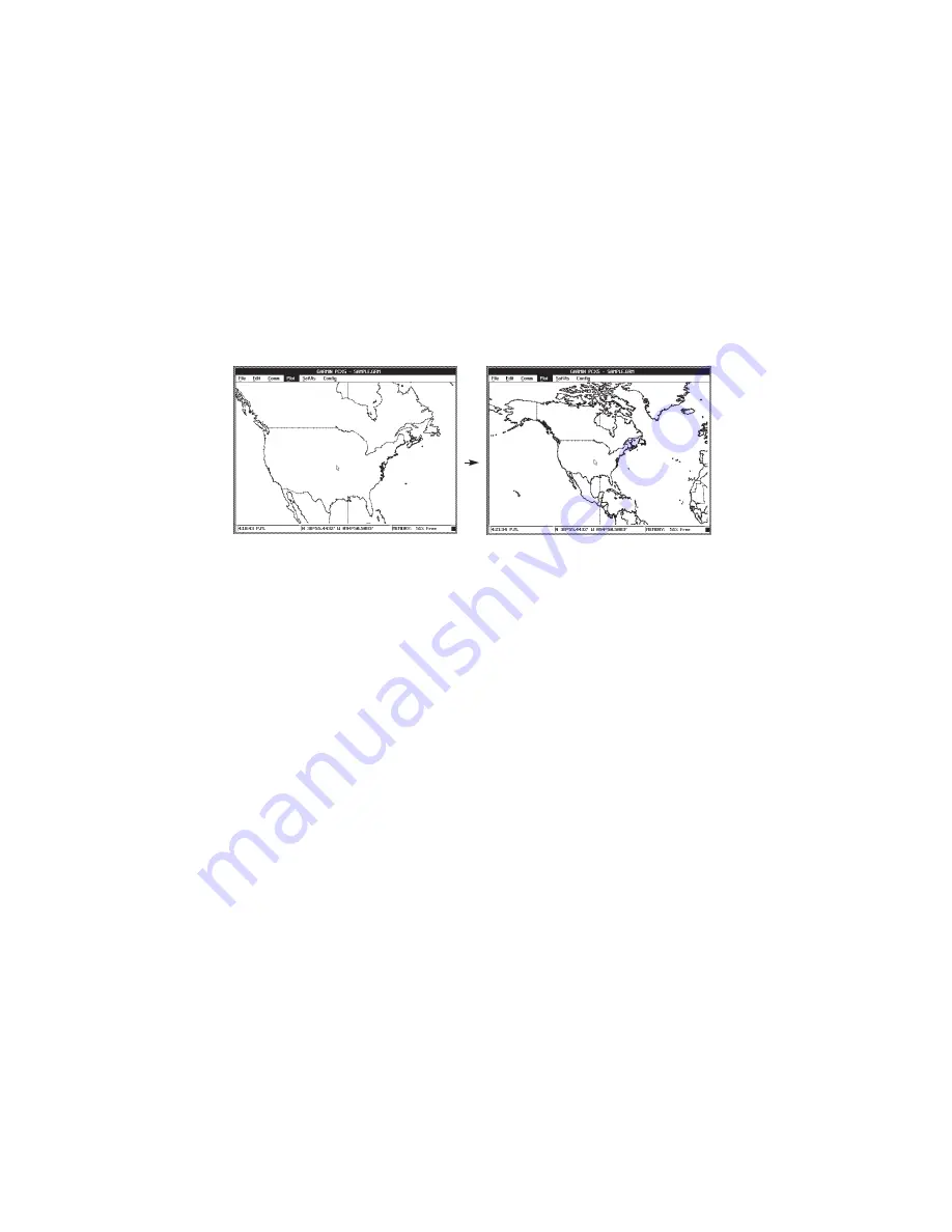
7.2  ZOOM OUT

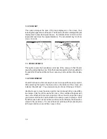
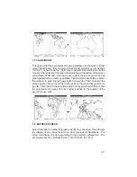
This option enlarges the area of the map displayed on the screen, thus
reducing the appearance of the plot.  The Zoom Out function enlarges the plot
display area to twice its original size (i.e., the distance from corner to corner
represents two times the original distance).  The accelerator key for Zoom
Out is <Ctrl+O>.

7.3  ZOOM EXTENTS

This option resets the boundaries and scale of the map such that the plot
spans the entire display area.  Note that new data points which are added to
the plot after it has been fitted to the screen may not be visible in the display
area.

7.4  ZOOM WINDOW

Zoom Window is an alternate way to zoom in on a specific area of your plot.
After selecting this option, the status line on the bottom of the screen will
indicate “Zoom Mode”.  The accelerator key for Zoom Window is <Ctrl+Z>.

Use the mouse to move the screen pointer near an area which you would like
to enlarge.  Click the left mouse button once.  A box outline will appear with
one corner attached to your screen pointer.  Move the screen pointer using
your mouse until the box outline frames the area you wish to enlarge.  Click
the left mouse button a second time and the area bounded by the box will be
scaled to fit your screen.  To cancel the zoom window (without pressing the
left mouse button a second time), press 

<

Esc

>.

7-2

Содержание PC150

Страница 1: ...PCX5 PCX5AVD PC150 PC SOFTWARE KIT OWNER S MANUAL Personal Nav Maintenance and Re ...

Страница 2: ...PCX5 PCX5AVD PC150 PC Software Kit OWNER S MANUAL ...

Страница 3: ... Inc 1200 E 151st Street Olathe KS 66062 USA 913 397 8200 GARMIN Europe Ltd Unit 5 The Quadrangle Abbey Park Romsey Hampshire SO51 9AQ UK GARMIN Asia Corp 3F No 1 Lane 45 Pao Hsing Road Hsin Tien Taipei Taiwan R O C Printed in Taiwan All rights reserved No part of this manual may be reproduced or transmitted inanyformorbyanymeans electronicormechanical includingphotocopying and recording for any p...

Страница 4: ...PCX5AVD PC150 software to its full potential Sample data has been provided to get you started The manual is divided into two parts Chapters 1 through 9 discuss features which are common to all three software packages All references in these chapters will be made to the PCX5 software but they applytoallsoftwarepackages Chapter10willhighlightthefeaturesspecific to the PCX5AVD and PC150 software Chap...

Страница 5: ...iderations 2 3 2 6 Installation 2 3 2 7 Error Messages 2 3 2 8 Upgrading From An Earlier Version 2 4 3 GETTING STARTED 3 1 3 1 Running PCX5 3 1 3 2 Accessing Menus and Selecting Options 3 2 3 3 Dialog Boxes 3 4 3 4 File Extensions 3 5 4 FILE MENU OPERATIONS 4 1 4 1 Open File to Plot 4 1 4 2 Save Plot to File 4 4 4 3 Save Plot As 4 4 4 4 Clear Plot 4 4 4 5 Convert to DXF Format 4 5 4 6 File Utiliti...

Страница 6: ...anac Data 6 6 6 3 Upload Data to Unit 6 7 6 4 Real time Plotting Logging 6 9 6 5 Comm Port 6 11 7 PLOT MENU OPERATIONS 7 1 7 1 Zoom In 7 1 7 2 Zoom Out 7 2 7 3 Zoom Extents 7 2 7 4 Zoom Window 7 2 7 5 Pan Window 7 3 7 6 Refresh Screen 7 3 8 SATVIS MENU OPERATIONS 8 1 8 1 SkyView 8 1 8 2 DOP Bar Chart 8 4 9 CONFIG MENU OPERATIONS 9 1 9 1 Units Configuration 9 1 9 2 Coordinate System Configuration 9...

Страница 7: ... 10 2 2 Waypoint Editor 10 3 10 2 3 Config Display Options 10 4 10 3 Additional Features 10 4 11 PC150 11 1 11 1 Setup and Installation 11 1 11 1 1 Checklist Editor 11 1 11 1 2 Schedule Editor 11 2 11 2 Additional Features 11 3 12 CONNECTING THE GPS UNIT TO A COMPUTER 12 1 APPENDICES A GLOSSARY A 1 B INDEX B 1 ...

Страница 8: ...ta for mapping navigation and planning applications Running on an IBM compatible PC the PCX5 software can be used to Download route waypoint proximity waypoint almanac and track datacollected by your GARMIN GPS unit for analysis plotting and processing Convertroute waypointandtrackfilestoDXFformatforinterfacing with other CAD systems e g AutoSketch Displaydigitalmapinrealtimeformappingandnavigatio...

Страница 9: ...its Menu means you would select the Config menu followed by the Units menu 1 3 SAMPLE FILES The original diskette contains several sample files that are copied to your program directory during installation These sample files can be used to experiment with the PCX5 program as you read through this manual These sample files include the following SAMPLE ALM Almanac file for the week the PCX5 program ...

Страница 10: ...oastal boundaries NOTE This file requires approximatelytwomegabytesofexpandedmemory toload Itisprovidedforyourownpersonaluseand GARMINassumesnoresponsibilityfortheaccuracy of the data Due to the large size of this database plotting efficiency will be decreased 1 3 ...

Страница 11: ... 2 SYSTEM REQUIREMENTS Minimum PC configuration required IBM compatible computer AT 386 or 486 640K memory 3 5 1 44 Mb floppy disk drive Hard Disk Drive EGA or VGA Graphics Adaptor Highly recommended configuration for speed considerations 386 or better processor 2 Megabytes RAM or more LIM 3 2 compatible Expanded Memory Driver EMS up to 16 Mb is used to store plot files VGA Graphics Adaptor Micros...

Страница 12: ...o the EGA or VGA graphics standards If necessary make sure that the proper graphics driver is installed in your system according to the type of monitor and video card being used The PCX5 software automatically detects the presence of an EGA or VGA graphics adaptor Some graphics adaptors may not be correctly detected You may force the software into EGA mode by specifying the EGA flag on the command...

Страница 13: ... the PCX5 program you should make a backup copy of your original diskette and place the original in a safe place To install the software onto a hard drive insert the diskette into the floppy drive i e drive A and run the installation program A INSTALL target directory where A is the appropriate floppy drive and target directory is the directory on the hard drive in which the software is to reside ...

Страница 14: ...e following file conver sions 1 PCX5 1 02 to PCX5 2 03 2 PC100S2 1 02 to PCX5 2 03 3 PCX5AVD 1 00 to PCX5 2 03 Figure 2 1 shows the main menu of the file conversion utility The current versionnumberofthefilesareshownontherightsideofthescreen Theuser canselect tag thedesiredfilestobeconvertedwiththespacebar Theuser can then select the desired conversion type by selecting options 1 2 or 3 The select...

Страница 15: ...ther from the current directory if available or from the program directory ega forces display into EGA mode see Section 2 3 mc n1 amount of conventional memory to allocate for plotting N1 is the amount in Kbytes If unspecified the program will use what it needs from available memory me n2 amountofexpandedmemorytoallocateforplotting N2 is the amount in 16K bytes If unspecified the program will use ...

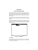
Страница 16: ...on Keyboard Speed Keys Press the underlined letter to select the desired menu option Mouse Click the left mouse button on the desired menu item the highlight bar will follow the pointer Or you may hold down the left mouse button as you move the pointer up down the menu and release the button to select the item under the highlight bar Any window or dialog box may be closed by pressing Alt F4 A shor...

Страница 17: ... data Route data Track file data Almanac data Display real time data in graphical form Communications port selection ThePlotmenuoffersoptionsforcustomizingthescreenplottingparameters Zoom in Zoom out Fit current plot to screen Zoom Extents Draw a window around a specific portion of screen plot and zoom in Pan to a specific point on your graph Refresh update screen TheSatVismenugivesyouoptionstopre...

Страница 18: ...uto Save function Accelerator keys are available for some menu options which enable you to select an option without pulling down the menu Accelerator keys which are availableforallPlotMenuoptionsandsomeFileMenuoptions aredisplayed beside the option name and are in the form Ctrl key where key is a specified letter For example pressing Ctrl I performs the Plot Menu Zoom In function 3 3 DIALOG BOXES ...

Страница 19: ...to the button which you want to set using Tab or use the mouse to move the pointer to the desired button and click the left mouse button Once the appropriate selections entries have been made move the cursor to the OK control button and press Enter or use the mouse to select the OK button with a single left button click This will cause the chosen menu operation to begin execution To exit the dialo...

Страница 20: ...ties print the current plot or exit the PCX5 program 4 1 OPEN FILE TO PLOT This option graphically plots data from an ASCII file to your PC screen using the parameters selected from the Plot and Config Menus described in Chapters 7 and 9 The input file required for this option may be a file created during a previous Download operation e g TRK RTE WPT PRX or a file in the GARMIN GRM format as descr...

Страница 21: ...ton to begin the operation If a plot is already loaded another dialog box will prompt you whether to append to or clear the existing plot Figure 4 3 APPEND PLOT DIALOG BOX A bar graph will be displayed as the file is loading The ESC key can be used to abort the load Figure 4 4 FILE LOAD BAR GRAPH ...

Страница 22: ...ndicate the file name of the last plot file loaded or saved GARMIN data files may contain multiple data types e g waypoints track proximity information etc The type of data displayed will depend on the settings in the Config Config Display Menu see Section 9 4 Once the file is displayed you can use the Plot Menu options Chapter 7 to customize the display of your data Config Menu options Chapter 9 ...

Страница 23: ...ved in the currently selected coordinate system format e g Latitude Longitude UTM UPS etc If more than one file is currently loaded thedatawillbesavedtothefileloadedlast namedonthetopdisplay line 4 3 SAVE PLOT AS This menu option allows you to save a copy of the data currently plotted on your PC monitor i e waypoints routes to an ASCII data file The data is saved in the currently selected coordina...

Страница 24: ... use this option enter the information required for the file to be converted drive directory and file name into the dialog box A second dialog box will appear to select the drive directory and file name for the output file The default file name is the input file name with a DXF extension Select OK to continue Figure 4 9 OUTPUT FILE DIALOG BOX Figure 4 10 CONVERSION OPTIONS DIALOG BOX 4 5 ...

Страница 25: ...option gives you the capability to delete copy or rename your DOS files To use this option fill in the file information drive directory and file name Select the DELETE button to delete the file the COPY button to copy the file to another drive directory or file name or the RENAME button to give the file a different name Figure 4 11 FILE UTILITIES BOX If COPY or RENAME is selected a second dialog b...

Страница 26: ...you to exit from the PCX5 program You may also exit without pulling down the File menu by using the accelerator key Ctrl X If the current plot has been modified a dialog box will remind you to save the file Figure 4 13 SAVE PLOT DIALOG BOX If theSAVEONEXIToptionisselectedontheConfigMenu seeSection9 8 all currently selected configuration parameters e g Comm Port Units Coordinates will be saved to t...

Страница 27: ...Edit menu allows you to create or modify waypoint and route files 5 1 WAYPOINT EDITOR Thewaypointeditorallowsyoutocreateormodifywaypoints Thewaypoints from the sample wpt waypoint file are listed as illustrated below Figure 5 2 WAYPOINT SELECT DIALOG BOX 5 1 ...

Страница 28: ...trol button from the Waypoint Select dialog box A blank Waypoint Edit dialog box will be displayed Enter thenewwaypointidentifieranditsdescription optional Enteritscoordinates directly or select a reference waypoint and enter a distance and bearing Select the OK button and the new waypoint will be added to the list If a plot is being displayed you may go directly to the Waypoint Edit dialog box sk...

Страница 29: ...r modify routes The routes from the sample rte plotted route file are listed as illustrated below Figure 5 4 ROUTE EDIT DIALOG BOX To enable graphical editing of an existing route select it with the left mouse button and it will be displayed in the edit field or use the arrow keys and ENTER Copy the selected route to an empty route by selecting the COPY button and designating the destination route...

Страница 30: ...the right mouse button and release it at the waypoint to be inserted The cursor will snap to the waypoint The route will be re drawn inserting the selected waypoint into the route immediately following the first selected waypoint To insert a waypoint without a mouse select the waypoint to precede the inserted waypoint and press Insert Move to the waypoint to be inserted into the route using the ar...

Страница 31: ...y displaying and editing a route View One Route mode will be the current configuration selection NOTE The PCX5 route editor will process up to a total of twenty routes and forty waypoints per route to maintain compatibility with a greater number of GARMIN GPS units Your GPS unit may have a lower route and waypoint capability See Appendix B for the route and waypoints per route capability of your u...

Страница 32: ...OTE The Range Bearing function will not work when in a Route Editing Mode i e when anything other than view none is selected on the Config Config Display Menu Figure 5 6 RANGE AND BEARING DIALOG BOX 5 6 ...

Страница 33: ...ng Data transferred between the PC and the unit is in a GARMIN proprietary binary format The PCX5 software converts the binary data to an ASCII readable file format for user editing The ASCII file format is GARMIN for Waypoint ProximityWaypoint Route orTrackFilesandYUMAforalmanac files While the data is being transferred a bar graph will indicate the progressofthetransfer TheESCkeycanbeusedtoabort...

Страница 34: ...cord R Route record T Track record track log file and Real time logging record select NMEA output format C Checklist record PC150 Only S Schedule record PC150 Only The data fields associated with the record follow the record type All fields must be separated by spaces Non trailing empty fields will contain one or more space characters At least one header line H record precedes each logical group o...

Страница 35: ... each record type is given in the sections that follow Note that the time given in the points created by the unit is UTC Time points created by the PC are in local PC Time 6 2 DOWNLOAD DATA FROM UNIT This option will transfer data from the unit into a PC From the sub menu select the type of data to download Waypoints Proximity Waypoints Routes Track log or Almanac Figure 6 2 DOWNLOAD DATA OPTIONS ...

Страница 36: ... I PCX5 2 00 H R DATUM IDX DA DF DX DY DZ M E WGS 84 100 0 000000e 00 0 000000e 00 0 000000e 00 0 000000e 00 0 000000e 00 H COORDINATE SYSTEM U LAT LON DM H IDNT LATITUDE LONGITUDE DATE TIME ALT DESCRIPTION PROXIMITY waypts W HOME N3519 3776 W08540 4503 07 JUN 93 14 26 47 9999 MY HOUSE 0 00000e 00 W MARINA N3510 6819 W08536 0333 07 JUN 93 14 29 17 9999 GOOD FOOD HERE 0 00000e 00 W BRIDGE N3522 834...

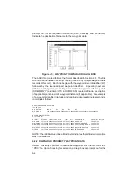
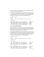
Страница 37: ...pts W HOME N3519 3776 W08540 4503 07 JUN 93 14 26 47 9999 MY HOUSE 1 00000e 03 W MARINA N3510 6819 W08536 0333 07 JUN 93 14 29 17 9999 GOOD FOOD HERE 2 00000e 02 W BRIDGE N3522 8349 W08551 1903 07 JUN 93 14 30 16 9999 COUNTY ROAD BRIDGE 1 25000e 03 W FCOVE N3459 3816 W08527 8865 07 JUN 93 14 31 15 9999 FISHING COVE 2 50000e 03 W WRECK N3502 5195 W08602 9741 07 JUN 93 14 32 44 9999 NAVIGATION HAZAR...

Страница 38: ...containalmanacdataforeachofthecurrentlyoperational satellites While the data is transferring a bar graph will monitor the rate of the data transfer Youmust download almanac data before running the SkyView or Bar Chart options on the SatVis Menu described in Chapter 9 or any third party planning software For best performance satellite almanac data should be under one month old An example of the inf...

Страница 39: ... file must be in the proper format You may use a file previously created during a waypoint route trackoralmanacdownload refertoSection6 2 oryoumay use a file which you have created using the waypoint or route editor see Chapter 5 Prior to beginning the Upload operation the proper COM port must be selected from the Comm Comm Port Menu see Section 6 5 or Chapter 11 for the GPS 150 and the input outp...

Страница 40: ...pt to upload a file which has more data than the unit can physically hold the unit will give you a memory full message and excess information in the file will be ignored Also if a specific route in your file contains more waypoints than is allowed in a route by the unit the route will be stored with the maximum number of waypoints allowed in a route and the excess waypoints will simply be stored a...

Страница 41: ...ns dialog box select between Add to Plot and ClearPlot AddtoPlot appendstothecurrentlydisplayedplot ClearPlot clears the current plot prior to plotting any data Figure 6 5 DISPLAY PLOT OPTIONS DIALOG BOX You must also select between File and Screen or Screen Only File and Screen logs data to a file while displaying it on your monitor you will be requestedtospecifyfileinformation ScreenOnly display...

Страница 42: ...em in which the file is formatted A third H record follows with one map datum record M record containing the following information M the record type R the altitude reference used E ellipsoid DATUM NAME the map datum used IDX the index number of the map datum DA delta earth radius DF delta flattening factor and DX DY and DZ delta earth center parameters Only one U record and one M record and their ...

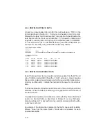
Страница 43: ...N I PCX5AVD 2 03 H R DATUM IDX DA DF DX DY DZ M G WGS 84 100 0 000000e 00 0 000000e 00 0 000000e 00 0 000000e 00 0 000000e 00 H COORDINATE SYSTEM U LAT LON DM H LATITUDE LONGITUDE DATE TIME ALT track T N3857 00698 W09444 76296 10 NOV 94 21 34 41 00340 T N3857 00698 W09444 76296 10 NOV 94 21 34 43 00341 T N3857 00698 W09444 76296 10 NOV 94 21 34 45 00340 T N3857 00698 W09444 76296 10 NOV 94 21 34 4...

Страница 44: ...screen Zoom Extents scales the plot to span the entire display area Pan Window allows you to reposition displayed data as you specify 7 1 ZOOM IN This option reduces the area of the map displayed on the screen thus amplifyingtheappearanceoftheplot TheZoomInfunctionreducesthearea displayed to half its original size i e the distance from corner to corner represents half the original distance The acc...

Страница 45: ... in the display area 7 4 ZOOM WINDOW Zoom Window is an alternate way to zoom in on a specific area of your plot After selecting this option the status line on the bottom of the screen will indicate Zoom Mode The accelerator key for Zoom Window is Ctrl Z Use the mouse to move the screen pointer near an area which you would like to enlarge Click the left mouse button once A box outline will appear w...

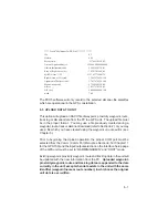
Страница 46: ... mouse button to select the position A solid line will now stretch between the from point and the screen pointer Move the pointer to the point on the graph that you want to pan to Click the left mouse button again and the graph will shift such that the selected point moves from its original position to the position of the second mouse click 7 6 REFRESH SCREEN Selectthisoptiontoredrawthegraphcurren...

Страница 47: ...tes in orbit over a selected location can be viewed as well as line and bar graphs which detail the best times for satellite availability Remember forSatVisdisplaystobeaccurate almanacdatamustberecent less than one month old or updated since any major change in the satellite constellation Almanac data is obtained by downloading it from the GPS unit see Section 6 2 5 Figure 8 1 SATVIS MENU 8 1 SKYV...

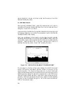
Страница 48: ...w display or select CURRENT TIME to enter the current local time Mask angle refers to the minimum acceptable satellite elevation No satellites below the angle of elevation entered will be included in the SkyView display Select between 3D and 2D Fixes designating whether a minimum of four 3D or three 2D satellites must be available Select OK to begin the SkyView display NOTE The SkyView display wil...

Страница 49: ...llite is useful in determining whetheritssignalwillbeblockedbybuildings mountainsorotherobstructions Horizontal Dilution of Precision HDOP and Position Dilution of Precision PDOP are displayed if the designated fix type 3D or 2D can be achieved ifnot theyappeardashed SeeAppendixAforadefinitionoftheseterms When the satellites appear they will be stationary To activate the satellites orbitalmotion s...

Страница 50: ... current date Again mask angle refers to the minimum acceptable satellite elevation Select between 3D or 2D Fixes specifying the number of satellites that must be visible Select OK to display the chart Figure 8 5 SATELLITE AVAILABILITY DOP BAR CHART The line graph on the top of the screen displays the HDOP Horizontal Dilution of Precision and PDOP Position Dilution of Precision at the selected pos...

Страница 51: ...he horizontal time scale is in one hour increments and the vertical scale shows the number of satellites visible The OK button in the top right corner of the screen or enter key is used to exit the satellite visibility screen A similar button below the OK button or a Cntl P can be used to print the screen ...

Страница 52: ...ption the dialog box shown below will be displayed allowing you to select the units to be used for Distance Error and Velocity For distance select one of the following Feet Statute Miles Nautical Miles Meters or Kilometers Next in the field below the distance units selection box enterthenumberofdecimalprecisiondigitstobedisplayedfordistance measurements NOTE Precision Digits fields will default to...

Страница 53: ... 9 2 COORDINATE SYSTEM CONFIGURATION This option allows you to display positions in one of six different coordinate systems Figure 9 3 COORDINATE SYSTEM DIALOG BOX In the dialog box displayed select between Latitude and Longitude in decimal degrees Latitude and Longitude in degrees decimal minutes Latitude and Longitude in degrees minutes decimal seconds UTM UPS Coordinates the British National Gr...

Страница 54: ...x shown below will be displayed Figure 9 4 DATUM CONFIGURATION DIALOG BOX Scroll through the list of map datums by left clicking the mouse pointer on the up down arrows on the right side of the datum list If USER is selected the User Datum dialog box will be displayed as illustratedbelow Entertheparametersdefiningthedifferencesbetweenthe WGS 84 earth model and the local datum s earth model DX DY a...

Страница 55: ...IONS DIALOG BOX You may turn on click so that an X appears in the box any number of Pot File Display Options Display Identifiers Displays identifiers or names beside all waypoints Display Descriptions Displays descriptions where applicable and available beside all waypoints Display Proximity Displays the proximity alarm radius as a circle around the appropriate waypoint s Display Points Displaystr...

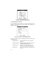
Страница 56: ... All Routes displays ALL routes in the displayed file View One Route allows you to specify one route to be displayed from the file View One Route will automatically be selected when performing graphic route editing see Section 5 2 Select the OK button to activate the selected display options 9 5 MISCELLANEOUS The Miscellaneous optionallowsyoutodefineaUTC to localtimedifference Enter the hours minu...

Страница 57: ...OS command line when starting the PCX5 program see Section 3 1 9 7 SAVE CONFIGURATION Select Save Configuration to save the currently selected parameters to a configuration file A dialog box will be displayed Specify the drive directory andfilenamefortheconfigurationfile Thedefaultfilenameis PCX5 CFG Select OK to save the configuration file 9 8 SAVE ON EXIT A check mark next to Save on Exit will i...

Страница 58: ...following PCX5AVD COM PCX5AVD main program README TXT may contain pertinent notes and information about PCX5AVD SAMPLE ALM sample almanac file for the week the PCX5AVD program was released SAMPLE PRX sample proximity waypoint file containing several proximity waypoints SAMPLE RTE sample route file containing several short routes SAMPLE TRK sample track log file containing over 150 points SAMPLE WP...

Страница 59: ...below Figure 10 1 MAIN MENU The following sections describe the menu differences that appear on the PCX5AVD program 10 2 1 CONVERT TO DXF FORMAT When converting ACSII data files to DXF format see Section 4 5 the DXF Conversion Options dialog box provides additional options for outputting Facility Name City and State to the DXF file This additional information is available for Airport and NAVAID wa...

Страница 60: ... Section 5 1 provides an additional information box to display Airport NAVAID Facility Name City State and Class for the selected waypoint Class information is provided for all waypoints and is displayed as Airport Intersection NDB VOR or User as applicable Figure 10 3 WAYPOINT EDIT DIALOG BOX 10 3 ...

Страница 61: ...lidaltitudeinformationisprovidedforairportlocationsinproximitywaypoint route and plot GRM data files Altitude information is included when downloading uploading andeditingthesedatafiles Examplewaypointand route files are shown on the following page Note that for non airport waypoints altitude is 9999 indicating valid altitude information is not available The default configuration file for the PCX5...

Страница 62: ...Y NAME CITY STATE CC CLASS waypts W HOME N3851 3190 W09445 4221 26 AUG 93 20 02 52 9999 MY HOUSE 0 00000e 00 4 W TOP N3908 2246 W09532 9475 27 AUG 93 03 38 08 9999 0 00000e 00 TOPEKA TOPEKA KS K3 3 W KPTS N3726 8552 W09443 8698 27 AUG 93 03 38 08 0290 0 00000e 00 ATKINSON MUN PITTSBURG KS K3 0 W RIS N3907 2256 W09435 7948 27 AUG 93 03 38 08 9999 0 00000e 00 RIVERSIDE KANSAS CITY MO K3 3 W OJC N385...

Страница 63: ... same command line switches as the PCX5AVD See Section 3 1 11 1 1 CHECKLIST EDITOR EDIT MENU The Checklist Editor is used to create checklists for certain procedures used before during or after flight These could include pre flight starting engines takeoff landing etc Up to nine checklists of 30 items each may be created and stored in the GPS 150 To use the Checklist Editor select it from the Edit...

Страница 64: ...ate a new one by simply typing the name with the SCH extension 11 2 To begin a new message file select Add to add a new message then type the message name After entering the message time press TAB or use the mouse to select the time field to the right of the message title field This field is used to enter the time the scheduled message will be displayed The format used is HH MM hours minutes Up to...

Страница 65: ...llowing settings are used on the GPS 150 For normal PC kit interfacing waypoint transfer etc Channel 2 IN Off OUT Off 9600 baud For real time plotting logging or NMEA communication Channel 2 IN Off OUT Plotting 4800 baud These are covered in the GPS 150 Pilot s Guide 11 3 11 2 ADDITIONAL FEATURES The default configuration file for the PC150 PC Kit is PC150 CFG ...

Страница 66: ...CHK C PITOT STATIC DRN C OXY DSCHARGE DSK C ENGINE INLET C SUMP DRAIN C 1 PRE START C BRAKE SET C OXYGEN CHECK C SWITCHES OFF C 2 STARTING ENGINES C FUEL COMPUTER ON C STARTER SW START C SPR BELOW 0 DEG SAMPLE SCHEDULE FILE H SOFTWARE NAME VERSION I PC150 2 03 S 0 CHECK FUEL1 01 00 S 1 CHECK FUEL2 02 00 S 2 CHECK FUEL3 03 00 ...

Страница 67: ... used to power some models during data transfer operations downloading uploading and real time plotting logging This connector is compatiblewiththevariousGARMINAC and12Vcigarettelighteradapters Providing external power is not required or available on all units however and data transfer can be done using the unit s main source of power These items may be purchased from your dealer or you may contac...

Страница 68: ...Precision HDOP is an indicator of the quality of a horizontal position latitude and longitude based on satellite geometry or position of the satellites with respect to each other A low HDOP value indicates better position accuracy PDOP Position Dilution of Precision PDOP is an indicator of the quality of a horizontal and vertical position latitude longitude and altitude based on satellite geometry...

Страница 69: ...digits 9 3 selection 9 2 D Datum selection 9 3 Dialog boxes 3 4 Disk caching 2 3 Display Options 9 4 DOP 8 4 DOP Bar Chart 8 4 Download Almanac 6 6 Checklist data 11 1 Data 6 3 Proximity Waypoint data 6 4 Route data 6 5 Schedule data 11 2 Track data 6 6 Waypoint data 6 3 DXF file conversion 4 5 E Edit menu 3 3 5 1 Exit 4 7 Expanded Memory 2 3 F File DXF conversion 4 5 extensions 3 5 menu 3 2 4 1 o...

Страница 70: ...5 5 Real time Plotting Logging 6 9 Record Types 6 2 Refresh screen 7 3 Route editor 5 3 Route file 6 5 Route view 9 5 S Sample files 1 2 Satellite Availability Bar Chart 8 4 SatVis menu 3 3 8 1 Save On Exit 4 7 9 6 Save Configuration 9 6 Save Plot As 4 4 Save Plot To File 4 4 Schedule Editor 11 2 Schedule file 11 4 SkyView 8 1 Speed keys 3 2 T Time Difference UTC to local 9 5 Track log file 6 6 U ...

Страница 71: ...ARMIN International Inc 1200 E 151st Street Olathe KS 66062 USA GARMIN Europe Ltd Unit 5 The Quadrangle Abbey Park Romsey Hampshire SO51 9AQ UK GARMIN Asia Corp 3F No 1 Lane 45 Pao Hsing Road Hsin Tien Taipei Taiwan R O C ...

Отзывы: