background image


GPS 152H Installation Instructions

to install the GPS 152H device on the mounting bracket:

1.  Loosely attach the two mounting knobs to the sides of the GPS 152H device.

2.  Insert the device into the mounting bracket. The bracket is designed for a tight fit to provide additional support when tilting the unit.

3.  Adjust the angle of the device, and tighten the two mounting knobs until the device is snug.

Installing the GPS 152H Wiring Harness

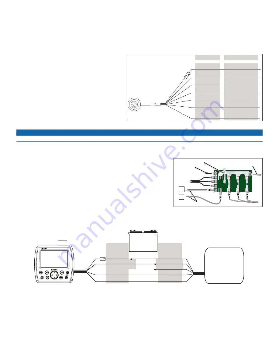
The GPS 152H device comes with a wiring harness that 

connects the device to power and to optional NMEA 0183 

devices.

notes: 

Use an AGC/ 3AG - 1.5 A replacement fuse.
If it is necessary to extend the power and ground wires, 

use 22 AWG wire.
You can wire the harness directly to the battery, or if 

your boat has an electrical system, you might be able to 

wire the harness to an unused holder on the fuse block. 

If you use the boat fuse block, remove the in-line fuse 

holder on the power wire of the harness..

notice

The maximum input voltage is 40 Vdc. Do not exceed this voltage because this can damage the device and void the warranty.

NOTE

: During a typical installation, use only the red and black wires. The other wires do not have to be connected for normal operation of the 

device. For information on connecting to a NMEA 0183 device, see below

.

Connecting the Wiring Harness to Power

1.  Use a test light or a voltmeter to determine the polarity of the voltage source.
2.  Connect the red (+ or positive) wire to the positive voltage terminal. (If you use the 

fuse block on the boat, route the positive connection through the fuse, as shown on the 

diagram.)

3.  Connect the black (- or ground) wire to the negative voltage terminal.
4.  Install or check the 1.5 A fuse (in the in-line fuse holder, or on the fuse block of the boat).

Connecting the Wiring Harness to a nMEa 0183 Device

You can connect the GPS 152H device to other NMEA compatible equipment, such as a 

DSC or AIS device. Refer to the wiring diagram for connecting the device to NMEA 0183-compatible devices.

Wiring a GPS 152H Device to a Standard nMEa 0183 Device

+

-

>

>

>

>

Red (power)
Black (ground)

Brown (in)

Blue (out)

Wire color

Power

Power ground
NMEA ground

NMEA Rx/A (+)

NMEA Tx/A (+)

NMEA 0183 

compliant device

Battery

10–0 Vdc

Fuse

3 A

Wire function

GPS 152H device


GPS 152H Wiring Harness

>

>

>

1

2

3

4

5

6

7

Pin 1—red

Unused

Pin 3—blue 

Alarm low

Wire Color

Wire Function

Power (10–0 Vdc)

Ground (power and 

NMEA)

NMEA com 1 Tx (out)

Pin —brown 

Pin 7—green

Pin 5—white

Pin 6—yellow

To the 

GPS 152H 

device

Fuse

1.5 

A

NMEA com 1 Rx (in)
NMEA com 2 Rx (in)

Pin 2—black

Fuse Block Example

+

2A

3A

-

+

Boat ground

1.5 A fuse

To 10–0 Vdc boat supply

To device

Fuse Block Example

+

2A

3A

-

+

Boat ground

1.5 A fuse

To 10–0 Vdc boat supply

To device

Содержание GPS 190-01219-91

Страница 1: ...uctions d installation FR istruzioni di installazione IT installationsanweisungen DE instrucciones de instalaci n ES instru es de Instala o PT installatie instructies NL installationsvejledning DA ase...

Страница 2: ......

Страница 3: ...mal viewing as you operate your boat The location allows for easy access to the keypad on the device The location is strong enough to support the weight of the device and protect it from excessive vib...

Страница 4: ...tage source 2 Connect the red or positive wire to the positive voltage terminal If you use the fuse block on the boat route the positive connection through the fuse as shown on the diagram 3 Connect t...

Страница 5: ...Wiring a GPS 152H Device to a Horn a Lamp or Both Relay 100 mA max coil current Horn Lamp Fuse 1 5 A Red Black ground Yellow alarm Wire color Battery 10 40 Vdc GPS 152H device 2010 Garmin Ltd or its...

Страница 6: ...ation L emplacement destin accueillir l appareil doit Offrir une visibilit optimale en cours de navigation Permettre d acc der facilement au pav num rique de l appareil Etre suffisamment r sistant pou...

Страница 7: ...nchez le fil rouge ou positif la borne de tension positive Si vous utilisez le bloc fusibles du bateau acheminez le branchement positif via le fusible comme illustr 3 Branchez le fil noir ou terre la...

Страница 8: ...ectionnels Raccordement d un appareil GPS 152H une corne une lampe ou les deux Relais courant sur bobine 100 mA max Corne Lampe Fusible 1 5 A Rouge Noir terre Jaune alarme Couleur du fil Batterie 10 4...

Страница 9: ...ione per il montaggio del dispositivo verificare che quest ultima Garantisca una visualizzazione ottimale durante la navigazione Consenta di accedere in modo semplice alla tastiera sul dispositivo Sia...

Страница 10: ...terminale di voltaggio positivo se si utilizza il blocco fusibili dell imbarcazione passare il collegamento positivo attraverso il fusibile come mostrato nel diagramma 3 Collegare il cavo nero o massa...

Страница 11: ...nipolari monocontatto Collegamento del dispositivo GPS 152H a un indicatore luminoso una sirena o entrambi Corrente max del rel di 100 mA Sirena Indicatore luminoso Fusibile 1 5 A Rosso Nero massa Gia...

Страница 12: ...ht auf das Ger t w hrend der Schiffsf hrung gew hren Der Montageort muss ungehinderten Zugriff auf das Tastenfeld des Ger ts erm glichen Der Montageort muss sich f r das Gewicht des Ger ts eignen und...

Страница 13: ...en Sie die rote Leitung am Pluspol der Spannungsquelle an Bei Verwendung des bootseigenen Sicherungsblocks verlegen Sie den Plus Anschluss ber die Sicherung siehe Zeichnung 3 Schlie en Sie die schwarz...

Страница 14: ...H an ein Horn eine Leuchte oder beides Relais Spulenstrom max 100 mA Horn Leuchte Sicherung 1 5 A Rot Schwarz Masse Gelb Alarm Leitungsfarbe Batterie 10 bis 40 V DC GPS 152H 2010 Garmin Ltd oder deren...

Страница 15: ...nstalar el dispositivo La ubicaci n debe proporcionar una visualizaci n ptima para que manejes la embarcaci n La ubicaci n debe permitir un acceso sencillo al teclado del dispositivo La ubicaci n debe...

Страница 16: ...e de fusibles de la embarcaci n realiza la conexi n positiva a trav s del fusible tal como se muestra en el diagrama 3 Conecta el hilo negro o de tierra al terminal de tensi n negativa 4 Instala o ver...

Страница 17: ...y unipolares Cableado del dispositivo GPS 152H a una bocina l mpara o a ambas Max corriente de la bobina del rel 100mA Bocina L mpara Fusible 1 5 A Rojo Negro tierra Amarillo alarma Color del hilo Ba...

Страница 18: ...guinte A localiza o permite a visibilidade ideal durante a navega o com a embarca o A localiza o permite f cil acesso ao teclado do dispositivo A localiza o suficientemente resistente para suportar o...

Страница 19: ...bloco de fus veis na embarca o encaminhe a liga o positiva atrav s do fus vel conforme ilustrado no diagrama 3 Ligue o cabo preto ou massa ao terminal de tens o negativa 4 Instale ou verifique o fus...

Страница 20: ...spositivo GPS 152H a uma buzina l mpada ou ambos Rel de 100 mA de corrente m xima da bobina Buzina L mpada Fus vel de 1 5 A Vermelho Preto massa Amarelo alarme Cor do cabo Bateria 10 40 V CC Dispositi...

Страница 21: ...ts moet optimaal zicht bieden terwijl u de boot bestuurt De bevestigingsplaats moet gemakkelijk toegang geven tot het toetsenbord van het toestel De bevestigingsplaats moet sterk genoeg zijn om het ge...

Страница 22: ...oltmeter om de polariteit te bepalen van de spanningsbron 2 Sluit de rode of positieve draad aan op de positieve voedingsaansluiting Als u het zekeringblok van de boot gebruikt sluit u de positieve dr...

Страница 23: ...beide Relais 100 mA max spoelstroom Hoorn Lamp Zekering 1 5 A Rood Zwart massa Geel alarm Kleur van draad Accu 10 40 Vdc GPS 152H toestel 2010 Garmin Ltd of haar dochtermaatschappijen Alle rechten vo...

Страница 24: ...n r du v lger en monteringsplacering til enheden Placeringen giver optimal visning mens du styrer fart jet Placeringen giver let adgang til enhedens tastatur Placeringen er st rk nok til at underst tt...

Страница 25: ...bestemme polariteten p sp ndingskilden 2 Tilslut den r de eller positiv ledning til den positive sp ndingstilslutning Hvis du bruger b dens sikringsblok skal du f re den positive tilslutning gennem s...

Страница 26: ...S 152H enhed til et horn en lygte eller begge dele Rel 100 mA maks spolestr m Horn Lygte Sikring 1 5 A R d Sort jord Gul alarm Ledningsfarve Batteri 10 40 V DC GPS 152H enhed 2010 Garmin Ltd eller det...

Страница 27: ...seuraavat seikat kun valitset laitteen kiinnityspaikkaa N kyvyys on optimaalinen kun ohjaat alusta Laitteen n pp imist voi k ytt helposti Paikka kest laitteen painon ja suojaa laitetta liialliselta t...

Страница 28: ...l pi kaavion mukaan 3 Liit musta johto eli maadoitusjohto negatiiviseen liit nt n 4 Asenna tai tarkista 1 5 A n sulake sis isess sulakepidikkeess tai veneen sulakerasiassa Johdinsarjan liitt minen NM...

Страница 29: ...minen torveen lamppuun tai molempiin Rele 100 mA max k min virta Torvi Lamppu Sulake 1 5 A Punainen Musta maadoitus Keltainen h lytys Johtimen v ri Akku 10 40 Vdc GPS 152H laite 2010 Garmin Ltd tai se...

Страница 30: ...1 5 mm 1 16 tommer for bore styrehullene Tenk p f lgende n r du velger hvor du skal montere enheten Stedet gir optimal utsikt n r du styrer b ten Stedet gir enkel tilgang til tastaturet p enheten Sted...

Страница 31: ...ingspolen Hvis du bruker b tens sikringsblokk legger du den positive koblingen via sikringen som vist i diagrammet 3 Koble til den svarte eller jord ledningen til den negative spenningspolen 4 Install...

Страница 32: ...et til et signalhorn en lampe eller begge deler Rel maks 100 mA coilstr m Signalhorn Lampe Sikring 1 5 A R d Svart jord Gul alarm Ledningsfarge Batteri 10 40 V DC GPS 152H enhet 2010 Garmin Ltd eller...

Страница 33: ...r optimal sikt f r man vrering av b ten Se till att enhetens knappsats r l ttillg nglig Platsen m ste vara tillr ckligt stadig f r att hantera enhetens vikt och skydda den fr n kraftiga vibrationer oc...

Страница 34: ...r da eller positiva ledningen till den positiva sp nningsterminalen Om du anv nder b tens s kringsplint leder du den positiva anslutningen genom s kringen som p bilden 3 Anslut den svarta eller negat...

Страница 35: ...alhorn en lampa eller b de och Rel 100 mA max spolstr m Signalhorn Lampa S kring 1 5 A R d Svart jord Gul larm Ledningsf rg Batteri 10 40 V dc GPS 152H enhet 2010 Garmin Ltd eller dess dotterbolag Med...

Страница 36: ...151st Street Olathe Kansas 66062 USA Garmin Europe Ltd Liberty House Hounsdown Business Park Southampton Hampshire SO40 9LR UK Garmin Corporation No 68 Jangshu 2nd Road Sijhih Taipei County Taiwan www...

Отзывы: