


Installation
Procedures
GNS 480 (CNX80) Installation Manual560-0982-01 Rev A
2-41
2.9 A
NTENNA
I
NSTALLATION AND
C
ONNECTIONS
The GNS 480 requires three antennas: Com antenna, GPS antenna, and Nav antenna. Follow the
manufacturer’s installation instructions for mounting the antennas.
2.9.1 C
OMM
A
NTENNA
The GNS 480 requires a standard 50
Ω
vertically polarized antenna. Follow the antenna manufacturer’s
installation instructions for mounting the antenna.
The antenna should be mounted on a metal surface or a ground plane with a minimum area of 18 x 18
inches. The antenna should be mounted a minimum of two feet away from GPS antennas.
The comm antenna should also be mounted as far apart as practical from the ELT antenna, preferably one
on top and the other on the bottom of the aircraft fuselage. Some ELTs have exhibited re-radiation
problems generating harmonics that may interfere with GPS signals. This can happen when the comm
(GNS 480 or any other comm) is transmitting on certain frequencies such as 121.15 or 121.175 MHz,
which may cause the ELT output circuit to oscillate from the signal coming in on the ELT antenna coax.
The antenna coax cable should be made of RG-142B or a comparable quality 50
Ω
coax. Assembly
instructions for the rear coax connector are included in Figure 2-11.
2.9.2 GPS
A
NTENNA
The mounting location and cable connections for the GPS antenna are very important. The antenna
should be mounted no closer than two feet from VHF comm transmitter antennas, six inches from other
antennas emitting less than 25 watts, and two feet from higher power antennas. See A-33 GPS Antenna
Installation Manual, p/n 560-0949-xx for more information on GPS antenna installation. Special care
should be taken to ensure that the GPS antenna is not mounted in close proximity to antennas that may
emit harmonic interference at the L1 frequency of 1575.42 MHz. Refer to AC 20-138A Airworthiness
Approval of Global Navigation Satellite System (GNSS) Equipment for additional information and
guidelines.
NOTE
The internal GNS 480 Com does not interfere with its own GPS receiver. However,
placement of the GNS 480 GPS antenna relative to other com transceivers and antennas
(including the GNS 480 Com antenna) is critical.
The connectors are included in the installation kit, and are intended for use with RG-142B size coax cable. If
using a different diameter coax, alternative connectors may be required. Assembly instructions for the
connectors are included in Figure 2-11. RG-142B cable can be used as long as the length is less than 35 feet.
For longer lengths, use low-loss 50
Ω
coax.
Suggestion:
Temporarily locate the GPS antenna with coax connected to the
GNS 480
and check the
GPS performance as described in the GPS Operation and Position test in the Post Installation Checkout
in section 3.3.2.1.2. Once a suitable location has been verified, then permanently mount the antenna.
NOTE
If using a GPS antenna that was already on the aircraft, or if mounting the antenna closer
than two feet from a comm antenna, conduct the GPS Operation and Position test in the
Post Installation Checkout on page 3-31. If the GNS 480 passes the test, then further
measures are not necessary.
Содержание GNS 480
Страница 1: ...GNS 480 CNX80 Color GPS Nav Com Installation Manual September 2004 560 0982 01 Rev A...
Страница 10: ...Table of Contents viii 560 0982 01 Rev A GNS 480 CNX80 Installation Manual NOTES...
Страница 30: ...General Information 1 20 560 0982 01 Rev A GNS 480 CNX80 Installation Manual NOTES...
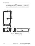
Страница 41: ...Installation Procedures GNS 480 CNX80 Installation Manual560 0982 01 Rev A 2 11 Figure 2 3 GNS 480 Dimensions...
Страница 126: ...Periodic Maintenance 6 2 560 0982 01 Rev A GNS 480 CNX80 Installation Manual NOTES...
Страница 144: ...Appendix B Serial Interface Specifications B 16 560 0982 01 Rev A GNS 480 CNX80 Installation Manual NOTES...
Страница 148: ...Appendix C Equipment Compatibility C 4 560 0982 01 Rev A GNS 480 CNX80 Installation Manual NOTES...
Страница 150: ...Appendix D Interconnect Diagrams D 2 560 0982 01 Rev A GNS 480 CNX80 Installation Manual NOTES...
Страница 182: ...Appendix E Acceptable Aircraft by Evaluation E 2 560 0982 01 Rev A GNS 480 CNX80 Installation Manual NOTES...
Страница 184: ...Appendix F Optional Accessories Not Supplied F 2 560 0982 01 Rev A GNS 480 CNX80 Installation Manual NOTES...
Страница 185: ......
Страница 186: ......


