Installation
Procedures
GNS 480 (CNX80) Installation Manual560-0982-01 Rev A
2-3
•
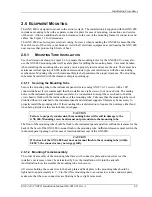
GPS antenna, Nav antenna and Com antenna.
•
External CDI/HSI indicator installed in the pilot’s primary field-of-view (or in the aircraft
manufacturer approved mounting location). This indicator must meet the following criteria:
1.
The course deviation needle shall have a full-scale deflection with a 150 mV deviation input.
2.
The valid flag shall be either a low-level input or superflag input.
3.
The TO/FROM flag shall be fully in view with a 250 mV input.
4.
The OBS resolver should be compatible with a standard 6-wire OBS interface:
H ............Reference output high
E.......... S3 COS input low
C.............Reference output low
F.......... S4 SIN input high
D ............S1 COS input high
G ......... S2 SIN input low
Any electrical zero crossing will work because the GNS 480 will calibrate out any errors.
•
External non-numeric glideslope indicator installed in the pilot’s primary field-of-view. This
indicator must meet the following criteria:
1.
The glideslope deviation needle shall have a full-scale deflection with a 150 mV deviation input.
2.
The valid flag shall be either a low-level input or superflag input.
NOTE
Exact specifications for the external CDI/HSI and glideslope indicator interfaces are
found in 1.3.9 Avionics Interfaces.
•
CDI/HSI source selection annunciator (only required for some installations – refer to 2.5.3.2 for
additional information describing when a source selection annunciator is required).
•
To take full advantage of the GNS 480 capabilities an optional altitude source is recommended for
automatic sequencing of course-to-altitude (CA) and heading-to-altitude (VA) leg types. If no
altitude data is provided to the GNS 480, CA and VA legs must be manually sequenced.
2.5.1.3 IFR GPS Installation
In order for the GNS 480 to be utilized for IFR GPS Navigation, the criteria in 2.5.1.2 must be met
and
the GNS 480 must be mounted within the acceptable field-of-view. Refer to 2.5.3.1 for determining
whether or not the GNS 480 is located within the acceptable field-of-view.
In certain instances, aircraft on the Approved Model List have a center radio stack located outside of the
acceptable field-of-view. These installations may only be approved for IFR operations under the AML if
the location has been previously approved by the FAA (ACO). Refer to Appendix E for a list of aircraft
that do not meet the acceptable field-of-view requirement above but have been evaluated by the FAA and
determined to be acceptable.
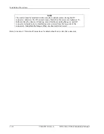
NOTE
If the GNS 480 installation is outside the acceptable field-of-view and the aircraft type is
not listed in Appendix E it does not mean that the installation is unacceptable – the FAA
has not yet evaluated it. The installation can be completed and the aircraft returned to
service pending an FAA evaluation of the installation, provided it is placarded “GPS
LIMITED TO VFR USE ONLY” in clear view of the pilot. IFR VOR/LOC/GS
operations are still permitted in this instance.
Contact Garmin AT for guidance on how to proceed in this case.
Содержание GNS 480
Страница 1: ...GNS 480 CNX80 Color GPS Nav Com Installation Manual September 2004 560 0982 01 Rev A...
Страница 10: ...Table of Contents viii 560 0982 01 Rev A GNS 480 CNX80 Installation Manual NOTES...
Страница 30: ...General Information 1 20 560 0982 01 Rev A GNS 480 CNX80 Installation Manual NOTES...
Страница 41: ...Installation Procedures GNS 480 CNX80 Installation Manual560 0982 01 Rev A 2 11 Figure 2 3 GNS 480 Dimensions...
Страница 126: ...Periodic Maintenance 6 2 560 0982 01 Rev A GNS 480 CNX80 Installation Manual NOTES...
Страница 144: ...Appendix B Serial Interface Specifications B 16 560 0982 01 Rev A GNS 480 CNX80 Installation Manual NOTES...
Страница 148: ...Appendix C Equipment Compatibility C 4 560 0982 01 Rev A GNS 480 CNX80 Installation Manual NOTES...
Страница 150: ...Appendix D Interconnect Diagrams D 2 560 0982 01 Rev A GNS 480 CNX80 Installation Manual NOTES...
Страница 182: ...Appendix E Acceptable Aircraft by Evaluation E 2 560 0982 01 Rev A GNS 480 CNX80 Installation Manual NOTES...
Страница 184: ...Appendix F Optional Accessories Not Supplied F 2 560 0982 01 Rev A GNS 480 CNX80 Installation Manual NOTES...
Страница 185: ......
Страница 186: ......


