


Av. Kit Install. Manual
190-00067-62 Rev. E
Page 5
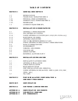
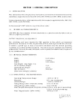
SECTION 1 GENERAL DESCRIPTION
1.1 INTRODUCTION
This manual describes the physical, mechanical, and electrical characteristics and the
installation requirements for the GNC 250, GNC 250XL and GPS 150XL Aviation Kits.
Unless stated otherwise, information found in this manual is applicable to the GNC 250,
GNC 250XL and GPS 150XL.
In this manual UNIT refers to any of the above units.
1.2
TECHNICAL CHARACTERISTICS
All UNITS offer the versatility of fixed installation in a panel mounted aviation rack as
well as complete portability.
For TSO Compliance, see Appendix A.
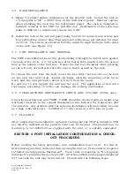
The conditions and tests required for TSO approval of this article are minimum
performance standards. It is the responsibility of those desiring to install this article on
or within a specific type or class of aircraft to determine that the aircraft operating
conditions are within the TSO standards. The article may be installed only if further
evaluation by the user/installer documents an acceptable installation and is approved
by the Administrator.
1.2.1 PHYSICAL CHARACTERISTICS
Width:
6.25 inches
Height:
2 inches
Depth:
5.65 inches
Unit Weight: (See Figure 3-4)
GA 56 Antenna Weight:
4 oz.
Aviation Rack Weight:
10 oz.
Max Air Speed:
Subsonic
(Structural rating for antenna)
1.2.2 OPERATIONAL CHARACTERISTICS
Operating Temperature Range:
-20
o
C to +55
o
C
Humidity:
95% non-condensing
Altitude Range:
-1,500 to 50,000 ft.
Voltage Range: (GNC 250/GNC 250XL)
10 to 15.1V DC
Voltage Range: (GPS 150XL)
10 to 33V DC
Power Requirements:(GNC 250/GNC 250XL)1.35A @ 13.8v (not transmitting)
5.5A @ 13.8V (transmitting)
Power Requirements: (GPS 150XL)
0.95A @ 13.8V
Содержание GNC 250
Страница 24: ...Av Kit Install Manual 190 00067 62 Rev E Page 24 FIGURE 1 1 PINOUT DEFINITION 37 PIN DSUB ...
Страница 26: ...Av Kit Install Manual 190 00067 62 Rev E Page 26 FIGURE 1 3A INTERCONNECT SCHEMATIC ...
Страница 27: ...Av Kit Install Manual 190 00067 62 Rev E Page 27 FIGURE 1 3B INTERCONNECT SCHEMATIC ...
Страница 28: ...Av Kit Install Manual 190 00067 62 Rev E Page 28 FIGURE 1 4 INTERCONNECT SCHEMATIC NOTES ...
Страница 30: ...Av Kit Install Manual 190 00067 62 Rev E Page 30 FIG 3 1 STUD MOUNT GA 56 ANTENNA INSTALLATION ...
Страница 31: ...Av Kit Install Manual 190 00067 62 Rev E Page 31 FIGURE 3 2 FLANGE MOUNT GA 56 ANTENNA INSTALLATION ...
Страница 32: ...Av Kit Install Manual 190 00067 62 Rev E Page 32 FIGURE 3 3 COAX CABLE INSTALLATION ...
Страница 34: ...Av Kit Install Manual 190 00067 62 Rev E Page 34 FIGURE 3 5 AVIATION RACK INSTALLATION ...
Страница 42: ...Av Kit Install Manual 190 00067 62 Rev E Page 42 ...
Страница 43: ...Av Kit Install Manual 190 00067 62 Rev E Page 43 ...
Страница 44: ...Av Kit Install Manual 190 00067 62 Rev E Page 44 ...


