


Av. Kit Install. Manual
190-00067-62 Rev. E
Page 18
304*
Waypoint identifier characters 1-3
305*
Waypoint identifier characters 4-6
306*
Waypoint latitude
307*
Waypoint longitude
Identification data
Label
(octal)
Description
377
Equipment identifier
371*
General Aviation equipment identifier
*These labels are formatted per the General Aviation Manufacturers Association
(GAMA) definition.
Note that the use of a 429 device w/o GAMA will cause the
loss of the above asterisked labels.
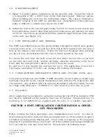
4.2.4 CDI CALIBRATION
Select the test page displaying CDI output calibration. Place the cursor on the
alignment field by using the outer knob. Use the inner knob to adjust the CDI
needle until it is centered. Once centered, turn the cursor off to complete the
calibration process.
4.2.5 CONFIGURATION
Select the Configuration Test Page. Change the selectable Strap and Fuel
selections to match that of the aircraft. The available options are:
Fuel:
av gas
Using Aviation gas (5.8 lbs/gal)
jet A
Using Jet A/Jet A-1 fuel (6.7 lbs/gal)
jet B
Using Jet B (JP-4) fuel (6.5 lbs/gal)
NOTE: The Fuel option is used to designate the type of fuel used so that
the correct fuel density will be used in calculations.
Remote Battery:
none
installed
NOTE: If installed is selected when a battery is not installed erroneous
voltages will be shown on the Power Test page and invalid battery
messages will be issued in normal operating modes.
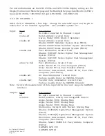
4.2.6 I/O CHANNEL 2
NOTE: This page is not found in the Test Pages but is included here to aid installation.
For more information see SET Pages in the Pilot's Guide (GPN 190-00067-50).
Select the I/O CHANNEL 2 Set Page. Change the selectable input and output to match
that of the installed equipment. The available options are:
Содержание GNC 250
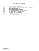
Страница 24: ...Av Kit Install Manual 190 00067 62 Rev E Page 24 FIGURE 1 1 PINOUT DEFINITION 37 PIN DSUB ...
Страница 26: ...Av Kit Install Manual 190 00067 62 Rev E Page 26 FIGURE 1 3A INTERCONNECT SCHEMATIC ...
Страница 27: ...Av Kit Install Manual 190 00067 62 Rev E Page 27 FIGURE 1 3B INTERCONNECT SCHEMATIC ...
Страница 28: ...Av Kit Install Manual 190 00067 62 Rev E Page 28 FIGURE 1 4 INTERCONNECT SCHEMATIC NOTES ...
Страница 30: ...Av Kit Install Manual 190 00067 62 Rev E Page 30 FIG 3 1 STUD MOUNT GA 56 ANTENNA INSTALLATION ...
Страница 31: ...Av Kit Install Manual 190 00067 62 Rev E Page 31 FIGURE 3 2 FLANGE MOUNT GA 56 ANTENNA INSTALLATION ...
Страница 32: ...Av Kit Install Manual 190 00067 62 Rev E Page 32 FIGURE 3 3 COAX CABLE INSTALLATION ...
Страница 34: ...Av Kit Install Manual 190 00067 62 Rev E Page 34 FIGURE 3 5 AVIATION RACK INSTALLATION ...
Страница 42: ...Av Kit Install Manual 190 00067 62 Rev E Page 42 ...
Страница 43: ...Av Kit Install Manual 190 00067 62 Rev E Page 43 ...
Страница 44: ...Av Kit Install Manual 190 00067 62 Rev E Page 44 ...


