


Av. Kit Install. Manual
190-00067-62 Rev. E
Page 13
3.3
CABLE INSTALLATION
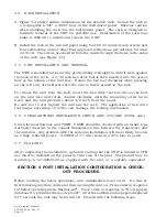
A. Route the coax cable to the rack location keeping in mind the recommendations
of Section 2. Secure the cable in accordance with good aviation practice.
B. Trim the coaxial cable to the desired length and install the BNC connector (330-
00087-00) per the cabling instructions on Figure 3-3. If the connector is provided
by the installer, follow the connector manufacturer's instructions for cable
preparation.
C. Contacts for the 37 and 26 pin connectors must be crimped into the individual
wires of the aircraft wiring harness. The following table lists contact part numbers
(for reference) and crimp tools:
Non- GARMIN part numbers shown are not maintained by GARMIN and conse-
quently are subject to change without notice.
NOTE: Alternate contacts for 18 AWG wire: As an alternate to the Positronic contacts
listed (and provided in the install kit), the installer may use contacts made by ITT
Cannon as follows: Socket contact - ITT Cannon p/n: 031-10007-001, Pin contact -
ITT Cannon p/n: 330-5291-055. These contacts require the use of a different crimp
tool positioner than that shown in the table, with part numbers as follows: Daniels
p/n: K250, Astro p/n: 616245, or ITT Cannon p/n: 980-00005-722.
See Appendix B for information regarding obsolete stamped type contacts.
Tools
Hand
Standard Density Connectors (size 20 contacts)
Hi Dens. Connector (size 22D)
Crimping
pin or socket contacts (20-24 AWG)
pin or socket contacts (18 AWG)
pin contacts (22-28 AWG)
Tool
positioner
insert/extract
positioner insert/extract
positioner
insert/extract
military p/n M22520/2-01
M22520/2-08
M81969/1-02
n/a
M81969/1-02
M22520/2-09
M81969/1-04
Positronic
9507
9502-5
M81969/1-02
9502-11
M81969/1-02
9502-3
M81969/1-04
ITT Cannon 995-0001-584 995-0001-604 980-2000-426* see note
274-7048-000* 995-0001-739
n/a
Amp
601966-1
601966-5
91067-2
n/a
n/a
601966-6
91067-1
Daniels
AFM8
K13-1
M24308/1-02
K774
M24308/1-02
K42
M24308/18-1
Astro
615717
615725
M81969/1-02
see note
M81969/1-02
615724
M81969/1-04
* Insert/extract tools from ITT Cannon are all plastic, others are plastic with metal tip.
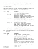
Contacts
Standard Density Connectors
Hi Dens. Connector
37 socket connector (J1 on unit)
9 pin connector (on battery pack)
26 pin connector (J2 on unit)
20-24 AWG socket contact
18 AWG socket contact
20-24 AWG pin contact
18 AWG pin contact
22-28 AWG pin contact
Garmin p/n 336-00022-00
336-00023-00
336-00024-00
336-00025-00
336-00021-00
military p/n M39029/63-368
n/a
M39029/64-369
n/a
M39029/58-360
Amp
205090-1
n/a
205089-1
n/a
204370-2
Positronic
M39029/63-368
FC6018D
M39029/64-369
MC6018D
M39029/58-360
ITT Cannon 031-1007-042
see note
330-5291-037
see note
030-2042-000
Содержание GNC 250
Страница 24: ...Av Kit Install Manual 190 00067 62 Rev E Page 24 FIGURE 1 1 PINOUT DEFINITION 37 PIN DSUB ...
Страница 26: ...Av Kit Install Manual 190 00067 62 Rev E Page 26 FIGURE 1 3A INTERCONNECT SCHEMATIC ...
Страница 27: ...Av Kit Install Manual 190 00067 62 Rev E Page 27 FIGURE 1 3B INTERCONNECT SCHEMATIC ...
Страница 28: ...Av Kit Install Manual 190 00067 62 Rev E Page 28 FIGURE 1 4 INTERCONNECT SCHEMATIC NOTES ...
Страница 30: ...Av Kit Install Manual 190 00067 62 Rev E Page 30 FIG 3 1 STUD MOUNT GA 56 ANTENNA INSTALLATION ...
Страница 31: ...Av Kit Install Manual 190 00067 62 Rev E Page 31 FIGURE 3 2 FLANGE MOUNT GA 56 ANTENNA INSTALLATION ...
Страница 32: ...Av Kit Install Manual 190 00067 62 Rev E Page 32 FIGURE 3 3 COAX CABLE INSTALLATION ...
Страница 34: ...Av Kit Install Manual 190 00067 62 Rev E Page 34 FIGURE 3 5 AVIATION RACK INSTALLATION ...
Страница 42: ...Av Kit Install Manual 190 00067 62 Rev E Page 42 ...
Страница 43: ...Av Kit Install Manual 190 00067 62 Rev E Page 43 ...
Страница 44: ...Av Kit Install Manual 190 00067 62 Rev E Page 44 ...


