190-01879-11
GMA 245/245R Installation Manual
Rev. 6
Page 3-8
Secondary Method:
Solder a Flat Braid (item 4,
) to the shield exposed through the window of the prepared cable
assembly (item 2,
). Ensure a solid electrical connection through the use of
acceptable soldering practices. Use care to avoid applying excessive heat that burns through the
insulation of the center conductors and shorts the shield to the signal wire. Slide a minimum 0.75
inches of Teflon heat shrinkable tubing (item 3,
) onto the prepared wire assembly and
shrink using a heat gun. The chosen size of heat shrinkage tubing must accommodate both the number
of conductors present in the cable and the Flat Braid (item 4,
) to be attached.
Teflon Heat Shrinkable Tubing:
Reference the following MIL-Spec for Teflon heat shrinkable tubing (M23053/5-X-Y).
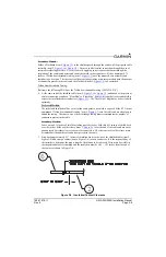
4. At the same end of the shielded cable (item 2,
) and ahead of the previous
shield termination, strip back “Float Min” to “Float Max” (
) length of jacket and shield to
expose the insulated center conductors (
). The “Ideal Float” length may be best to build
optimally.
Preferred Method:
The jacket and shield should be cut off at the same point so no shield is exposed. Slide 0.75 inches
minimum of Teflon heat shrinkable tubing (item 5,
) onto the cable and use a heat gun to
shrink the tubing. The chosen size of heat shrinkage tubing must accommodate the number of
conductors present in the cable.
Secondary Method:
Leave a max 0.35 inches of shield extending past the jacket. Fold this 0.35 inches of shield back
over the jacket. Slide a solder sleeve (item 5,
) over the end of the cable and use a heat
gun approved for solder sleeves to secure the connection. The chosen size of solder sleeve must
accommodate the number of conductors present in the cable.
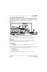
5. Strip back approximately 0.17 inches of insulation from each wire of the shielded cable (item 2,
Figure 3-4) and crimp a contact (item 6, Figure 3-4) to each conductor. It is the responsibility of
the installer to determine the proper length of insulation to be removed. Wire must be visible in
the inspection hole after crimping and the insulation must be 1/64 – 1/32 inches from the end of
the contact as shown in Figure 3-4.
Figure 3-4 Insulation/Contact Clearance
6
2


