background image

2 - NAV PAGES

33

190-00356-00 Rev B

Map Page

Map Symbols

Various symbols are used to distinguish between 

waypoint types. The identifiers for any on-screen 
waypoints can also be displayed. (By default the iden-
tifiers are enabled). Special-use and controlled airspace 
boundaries appear on the map, showing the individual 
sectors in the case of Class B or Class C airspace. 
The following symbols are used to depict the various 
airports and navaids on the 

map page


Airport with hard surface runway(s); Primary runway shown


Airport with soft surface runway(s) only


Private Airfield 


Intersection


VOR 


VORTAC


VOR/DME   


TACAN


DME 


NDB


Localizer   


Locator Outer Marker


Heliport

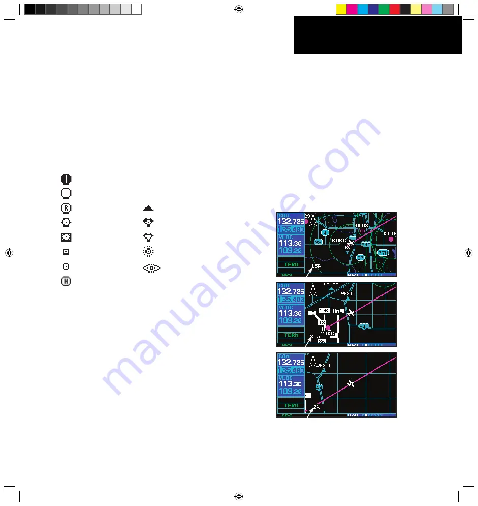
Map Range

The map display can be set to 23 different scale 

settings from 500 feet to 2000 nautical miles (statute 
and metric units are also available). The scale is indi-
cated in the lower left-hand corner of the map display, 
and represents the top-to-bottom distance covered by 
the map display. 

To select a map Range: 

1.   Press the 

up arrow

 sde of the 

RNG

 key to 

zoom out to a larger map area. 

2.   Press the 

down arrow

 sde of the 

RNG

 key 

to zoom n to a smaller map area and more 
detal. 

190-00356-00_0B.indd   33

9/7/2007   2:49:08 PM

Содержание 400W Series

Страница 1: ...Pilot s Guide Reference 400W Series 190 00356 00_0B indd 1 9 7 2007 2 48 53 PM...

Страница 2: ...vided herein no part of this manual may be reproduced copied transmitted disseminated downloaded or stored in any storage medium for any purpose without the express written permission of Garmin Garmin...

Страница 3: ...nd decode the satellite signals In such event the interference may be reduced or eliminated by switching off the source of interference or moving the GPS receiver away from it CAUTION The electronic c...

Страница 4: ...ived including interference that may cause undesired operation To obtain accessories for your 400W series please contact your Garmin dealer Help us better support you by completing our on line registr...

Страница 5: ...nectors Pilot s Guide Quick Reference 400W 500W Series Display Interfaces Addendum 400W 500W Series Garmin Optional Display Interfaces Addendum GNS 400W 500W series Simulator Training CD ROM Database...

Страница 6: ...FOR A PARTICULAR PURPOSE STATUTORY OR OTHERWISE THIS WARRANTY GIVES YOU SPECIFIC LEGAL RIGHTS WHICH MAY VARY FROM STATE TO STATE IN NO EVENT SHALL GARMIN BE LIABLE FOR ANY INCIDENTAL SPECIAL INDIRECT...

Страница 7: ...nge 33 Map Page Auto Zoom 34 Map Panning 35 Map Direct To 36 Airspace Information on the Map 36 Map Page Options 37 Map Setup 37 Data Fields on the Map 40 Selecting Desired On Screen Data 40 Restoring...

Страница 8: ...hes 110 Enabling Autopilot Outputs for the King KAP140 KFC225 112 Section 6 WPT Pages 113 WPT Page Group 113 Duplicate Waypoints 115 Airport Runway Page 117 Airport Frequency Page 118 Airport Approach...

Страница 9: ...ettings 174 Section 10 Fault Detection Exclusion 175 Detection and Exclusion 175 Section 11 Messages Abbreviations and Navigation Terminology 177 Messages 177 Turn Advisory and Arrival Annunciations 1...

Страница 10: ...INTRODUCTION viii 190 00356 00 Rev B Blank Page 190 00356 00_0B indd 8 9 7 2007 2 48 55 PM...

Страница 11: ...program the GPS 400W may be used for oceanic or remote operations For the latest in graphical and textual weather information the GPS 400W can connect to XM Satellite Radio s XM WX Weather Service via...

Страница 12: ...the next three pages provide a general overview of the primary function s for each key and knob This Takeoff Tour section is intended to provide a brief overview of the primary functions of your 400W...

Страница 13: ...Right hand Keys and Knobs Right hand Keys and Knobs R The range key RNG allows you to select the desired map scale Use the up arrow side of the key to zoom out to a larger area or the down arrow side...

Страница 14: ...See Sections 11 and 9 for more information on messages and unit settings The flight plan key FPL allows you to create edit activate and invert flight plans as well as access approaches departures and...

Страница 15: ...fields etc the pictures shown here may not exactly match what you see on your 400W series unit Prior to using your unit for the first time we recommend that you taxi to a location that is well away f...

Страница 16: ...board and fuel flow may be manually entered if your installation does not include connection to sen sors which automatically provide these figures To enter fuel capacity fuel on board or fuel flow fig...

Страница 17: ...ries unit can hold up to nine check lists with up to 30 entries in each checklist 2 Turn the large right knob to select the desired checklist then follow the steps in Section 9 Aux Pages Utility Page...

Страница 18: ...eiver s cur rent operating condition To return to the previous page after viewing a message press the MSG key again The satellite status page shows the ID num bers for the satellites and the relative...

Страница 19: ...select the desired megahertz MHz value For example the 135 portion of the frequency 135 325 3 Turn the small left knob to select the desired kilohertz kHz value For example the 325 portion of the freq...

Страница 20: ...lects the page group NAV WPT AUX or NRST The small right knob selects the desired page within a group To quickly select the default NAV page press and hold the CLR key Small right knob to select pages...

Страница 21: ...ght knob to change page groups Large right knob to select pages with the group a Flight plan pages are selected by pressing the FPL key and using the small right knob to select the desired page FPL Gr...

Страница 22: ...lan ning or unit settings and listings for nearest NRST airports or other facilities To select the desired page group turn the large right knob until a page from the desired group is displayed To sele...

Страница 23: ...e en route ETE See Sec tion 11 for definitions of these navigation terms The default NAV page is selected by pressing and holding the CLR key or turning the small right knob Active Leg of Flight Plan...

Страница 24: ...inimum safe altitude and ground track See Section 11 for definitions of these navigation terms Map Page Data Fields Present Position Map Display Map Scale with declutter value Desired Track The map pa...

Страница 25: ...entifier field in the GPS window Turn the small right knob to display the list of airports departure arrival and en route for your flight plan or direct to Continue to turn the small right knob until...

Страница 26: ...ection 3 for more information 2 Turn the small right knob to enter the first letter of the destination waypoint identifier The destination waypoint may be an airport VOR NDB intersection or user waypo...

Страница 27: ...ist of available proce dures for the arrival when using approaches or STARs or departure when using SIDs airport 3 Turn the small right knob to select the desired procedure and press ENT 4 For approac...

Страница 28: ...under the NRST group Nearest airport page Nearest intersection page Nearest NDB page Nearest VOR page Nearest user waypoints page Nearest ARTCC page Nearest FSS page Nearest airspace page To display...

Страница 29: ...he small right knob to remove the cursor and turn the small right knob to display the desired information page The nearest airport page may be used in conjunc tion with the direct to key to quickly se...

Страница 30: ...n the message MSG annunciator located directly above the MSG key will flash to alert you to the airspace message See Section 9 Aux Pages Setup 1 for information on enabling airspace alert messages To...

Страница 31: ...o use for navigation Additional information about flight plans can be found in Section 4 Flight Plans To create a new flight plan 1 Press the FPL key and turn the small right knob to select the flight...

Страница 32: ...plan catalog It replaces any flight plan which currently exists in flight plan 00 To activate the new flight plan 1 On the Flight Plan Catalog page press the small right knob to activate the cursor R...

Страница 33: ...t corner of the screen while transmitting Volume COM radio volume is adjusted using the COM power volume knob Turn the COM power volume knob clockwise to increase volume or counterclock wise to decrea...

Страница 34: ...at this location while you are transmitting NOTE The tuning cursor will normally appear in the COM window unless placed in the VLOC window by pressing the small left knob When the tuning cursor is in...

Страница 35: ...right knob until the nearest pages appears Finally if necessary turn the small right knob to display the nearest airport page 2 Press the small right knob momentarily to place the cursor on the airpo...

Страница 36: ...cursor on the airport identifier field To the left of this field appears Departure En Route or Arrival depending on the placement of the dis played airport within your flight plan 3 Turn the small rig...

Страница 37: ...00 MHz emergency frequency Note Under some circumstances if the com sys tem loses communication with the main system the radio will automatically tune to 121 500 MHz for transmit and receive regardles...

Страница 38: ...frequency list through the Standby frequency box the list will wrap from the bottom of the list back up to the top skipping any empty preset positions Preset Com Frequencies are only available with S...

Страница 39: ...e between the default NAV and map pages two of the most frequently used pages Other pages are provided to list frequencies for your flight plan show your current position display current satellite rec...

Страница 40: ...he approach You may also manually select the desired scale set ting as outlined in the Aux Setup section The graphic CDI shows your position at the center of the indicator relative to the desired cour...

Страница 41: ...e error TKE Ground track TRK Vertical speed required VSR Cross track error XTK If no flight plan or direct to destination has been selected only speed track altitude and minimum safe altitude data may...

Страница 42: ...databases of the 400 500 series and the 400W 500W are incompatible so you may not mix systems Map Page The second NAV page is the map page which dis plays your present position using an airplane symbo...

Страница 43: ...Primary runway shown Airport with soft surface runway s only Private Airfield Intersection VOR VORTAC VOR DME TACAN DME NDB Localizer Locator Outer Marker Heliport Map Range The map display can be se...

Страница 44: ...lay but the airport and navaid detail will remain The Setup Map option allows you to define the maximum scale at which each map feature will appear This provides you with complete control to minimize...

Страница 45: ...r left counterclockwise 4 To cancel the panning function and return to your present position press the small right knob When the target pointer is placed on an object the name of that object will be h...

Страница 46: ...floor ceiling limits and controlling agency directly from the map To view airspace information for an on screen special use or controlled airspace 1 Use the panning function see previous page to place...

Страница 47: ...ists the group names and available settings Feature Description Map Orientation AutoZoom Land Data Avia tion Data Weather Lightning Mode Symbol when applicable Traffic Traffic Mode Symbol Label when a...

Страница 48: ...0 NM through each lower scale stopping at 1 0 NM as you approach your destination waypoint 5 To enable disable background land data or all Jeppesen aviation data turn the small right knob to select Ma...

Страница 49: ...ress ENT when finished Note that if a fuel system is providing current fuel flow the fuel flow field will default to this value 7 The flashing cursor moves to the ground speed GS field Use the small a...

Страница 50: ...retained the next time you view the page Trip Planning To perform trip planning operations 1 Select Trip Planning from the flight planning page 2 The current trip planning leg mode is dis played at th...

Страница 51: ...t TAS Winds To calculate density altitude true airspeed winds aloft 1 Select Density Alt TAS Winds from the flight planning page 2 The flashing cursor highlights theindicated alti tude INDALT field Us...

Страница 52: ...ressing the MENU key or while on the Flight Planning page by scrolling down to Crossfill and pressing ENT From Default NAV Page From Flight Plan Pages Automatic Operation If both units are set to auto...

Страница 53: ...ng Crossfill from the flight planning page Flight Plan transfer any stored flight plan to from a second 400W 500W series unit by selecting the flight plan by number This option is the default when sel...

Страница 54: ...hours min utes hhh mm Event based messages expire at a specific date and time Press ENT when finished To edit a scheduled message 1 Select Scheduler from the flight planning page 2 The flashing curso...

Страница 55: ...rip Statistics provides readouts for trip odom eters average speed and maximum speed These readouts are resettable individually or all at once by pressing MENU to display an options window RAIM Predic...

Страница 56: ...the current Jeppesen database type effective date and expiration date along with the version and type of built in land database Terrain Database Versions The Terrain Database Versions Page displays th...

Страница 57: ...ately follow the new checklist step 3 Turn the small and large right knobs to enter the new checklist step Press ENT when finished To delete a checklist or all checklists 1 With the checklists page di...

Страница 58: ...he time field Press CLR followed by ENT To record or reset the departure time 1 Select Flight Timers from the utility page 2 Turn the large right knob to highlight the reset mode field under Departure...

Страница 59: ...RAIM Prediction To predict RAIM availability 1 Select RAIM Prediction from the utility page 2 The flashing cursor highlights the waypoint field Use the small and large right knobs to enter the identi...

Страница 60: ...to the CDI Alarms section of Aux pages Setup 1 for specific information regarding RAIM protection limits Sunrise Sunset To calculate sunrise and sunset times at any waypoint or your present position 1...

Страница 61: ...available from this page Reach these pages by turning the small or large right knobs and then press ENT Press CLR or the small right knob to return to the utility page Setup 1 Page The Setup 1 page pr...

Страница 62: ...esent full scale deflection for the CDI to either side The default setting is Auto At this setting the CDI scale is set to 2 0 NM during the en route phase of flight Within 31 NM of your destination a...

Страница 63: ...n miles of your present position Grid MORAs are one degree latitude by one degree longitude in size and clear all reference points within the grid by 1000 feet in areas where the highest reference poi...

Страница 64: ...e left and the swing arm handle at the bottom front NOTE There are two data card slots on the face of the 400W series The Jeppesen NavData card should be inserted in the left most slot The second slot...

Страница 65: ...ical with WAAS Dynamics 1000 kt maximum velocity VHF COM PERFORMANCE GNS 430W only Channels 760 25 kHz spacing or 2280 8 33 kHz spacing Frequency Range 118 000 MHz to 136 992 MHz Transmit Power 10 wat...

Страница 66: ...e time Because of the tighter protection limit on approaches there may be times when RAIM is not available The 400W series unit automatically monitors RAIM and will warn you with an alert message see...

Страница 67: ...ns Can I file slant Golf G using my GPS Yes you may file your flight plan as G if your 400W series unit is an authorized IFR installation The 400W series is a TSO C146a Gamma 3 Class 3 authorized GPS...

Страница 68: ...equencing An example of this operation is an approach which begins with a holding pattern at the ini tial approach fix IAF Section 5 Flying an Approach with a Hold for more information on the SUSP ann...

Страница 69: ...A flashing turn advisory LT or RT TO NOW will appear in the lower right corner of the screen when you are to begin the turn Set the HSI to the next DTK value and begin the turn 3 The To From indicato...

Страница 70: ...pleted at the FAF Full Scale deflection and defined path for VTF approach Why does my CDI not respond like a VOR when OBS mode is active Unlike a VOR the CDI scale used on GPS equipment is based on th...

Страница 71: ...nt on See Section 4 Active Flight Plan Leg Selection for information on activat ing a specific flight plan leg To activate a new approach for the same airport se lect the new procedure from the proced...

Страница 72: ...tivate 82 Airport 120 DME arc 92 Hold 89 ILS 102 Localizer 110 LPV 107 Procedure turn 84 VTF 82 95 Approach Channel 122 ARINC 181 191 Arrival 17 51 75 78 81 122 168 177 195 ARTCC 18 26 133 134 138 139...

Страница 73: ...elling 65 Flight plan destination 63 Manual course 65 Nearest airport 63 Shortcuts 64 Display backlight 171 172 Distance measurements 39 DME Arc 92 Dual units 32 Duplicate waypoint 115 E E6B 149 150 E...

Страница 74: ...ic variation 166 168 Map Auto zoom 34 Create user waypoint 129 Data fields 40 Datum 166 170 181 Page 14 32 Panning 35 Scale 33 117 Setup 37 Symbols 33 MAPR 83 Measure dist 39 Menu 3 Messages 4 8 177 M...

Страница 75: ...s 17 123 Slant golf 193 Software version 159 164 Sort list 72 Special use airspace 20 Specifications 191 Squelch 23 Standard package iii Standby frequency 9 STARs 17 75 122 Stormscope 182 Stuck microp...

Страница 76: ...rt 116 Airport frequency 118 Airport runway 117 Approach 120 Arrival 122 City 114 Departure 123 Duplicate 115 Facility 114 Identifier 114 Intersection 125 Modify user 129 NDB 125 User 127 138 VOR 126...

Страница 77: ...190 00356 00_0B indd 203 9 7 2007 2 50 14 PM...

Страница 78: ...U S A Garmin AT Inc 2345 Turner Rd S E Salem Oregon 97302 U S A Garmin Europe Ltd Liberty House Hounsdown Business Park Southhampton SO40 9RB U K Garmin Corporation No 68 Jangshu 2nd Road Shijr Taipei...

Отзывы: