13-25-629 v03 Page 43
ADDITION OF OIL BETWEEN CHANGES
must be made when the oil level is below the minimum level of
the sight glass as read while the unit is completely off and blown down, and the foam has settled out.
1.
Be sure the unit is completely off and that no air pressure is in the oil reservoir.
2.
Disconnect, lockout and tagout the power supply to the starter.
3.
Wipe away all dirt around the oil filler plug located on top of the oil sump.
4.
Remove the oil filler plug and add oil as required to return the oil level to the middle of the sight
gauge.
5.
Install oil filler plug, run and check for leaks.
DO NOT OVERFILL
(you should see oil slightly above the full line after running fully loaded and then
shutting down the machine and allowing the foam to settle out). The quantity required to raise the oil level
from “ADD” to “FULL” is shown on
. Repeated addition of oil between oil changes may indicate
excessive oil carry-over and should be investigated.
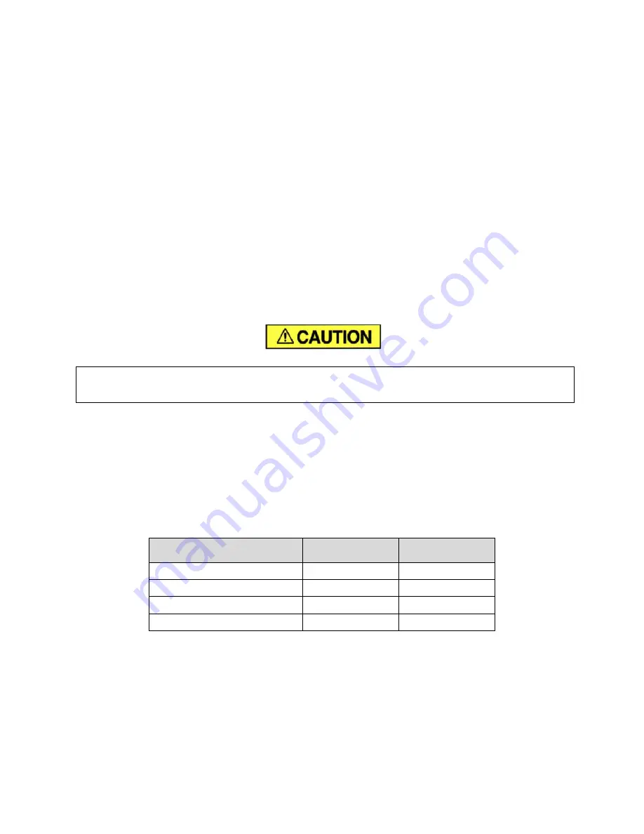
Excessive oil carry-over can damage equipment. Never fill oil reservoir above
the “FULL” marker.
OIL CHANGE INTERVAL
- Recommended oil change intervals are based on oil temperature, see Figure
5-2 for typical trends for the standard lubricant (AEON 4000) and a synthetic lubricant (AEON 9000SP).
Consult Gardner Denver for additional lubricant types available for your compressor.
When operating conditions are severe (very dusty, high humidity, etc.), it will be necessary to change the
oil more frequently. Operating conditions and the appearance of the drained oil must be surveyed and the
oil change intervals planned accordingly by the user. Gardner Denver offers a free oil analysis program
with the AEON lubricants, and we recommend a sample be sent in at 100 hours on a new unit.
Discharge Temperature
AEON 4000
Change Interval
AEON 9000SP
Change Interval
Up to 180°F (82°C)
4000 hrs.
8000 hrs.
180° to 190°F (82°C to 88°C)
3000 hrs.
6000 hrs.
190° to 200°F (88°C to 93°C)
2000 hrs.
4000 hrs.
200°F+ (93°C)
1000 hrs.
2000 hrs.
Figure 5-2 Oil Change Interval
Содержание L4-5C
Страница 24: ...13 25 629 v03 Page 24 FIGURE 4 2 WIRING DIAGRAM 208 230 460V 60 Hz 306ECA546 B Ref Drawing Page 1 of 3...
Страница 25: ...13 25 629 v03 Page 25 FIGURE 4 3 WIRING DIAGRAM 208 230 460V 60 Hz 306ECA546 B Ref Drawing Page 2 of 3...
Страница 26: ...13 25 629 v03 Page 26 FIGURE 4 4 WIRING DIAGRAM 208 230 460V 60 Hz 306ECA546 B Ref Drawing Page 3 of 3...
Страница 27: ...13 25 629 v03 Page 27 FIGURE 4 5 WIRING DIAGRAM 380V 60 Hz 303ECA546 B Ref Drawing Page 1 of 3...
Страница 28: ...13 25 629 v03 Page 28 FIGURE 4 6 WIRING DIAGRAM 380V 60 Hz 303ECA546 B Ref Drawing Page 2 of 3...
Страница 29: ...13 25 629 v03 Page 29 FIGURE 4 7 WIRING DIAGRAM 380V 60 Hz 303ECA546 B Ref Drawing Page 3 of 3...
Страница 30: ...13 25 629 v03 Page 30 FIGURE 4 8 WIRING DIAGRAM 575V 305ECA546 A Ref Drawing Page 1 of 3...
Страница 31: ...13 25 629 v03 Page 31 FIGURE 4 9 WIRING DIAGRAM 575V 305ECA546 A Ref Drawing Page 2 of 3...
Страница 32: ...13 25 629 v03 Page 32 FIGURE 4 10 WIRING DIAGRAM 575V 305ECA546 A Ref Drawing Page 3 of 3...
Страница 33: ...13 25 629 v03 Page 33 Figure 4 11 WIRING DIAGRAM 230V 1 Phase 307ECA546 D Ref Drawing Page 1 of 4...
Страница 34: ...13 25 629 v03 Page 34 Figure 4 12 WIRING DIAGRAM 230V 1 Phase 307ECA546 D Ref Drawing Page 2 of 4...
Страница 35: ...13 25 629 v03 Page 35 Figure 4 13 WIRING DIAGRAM 230V 1 Phase 307ECA546 D Ref Drawing Page 3 of 4...
Страница 36: ...13 25 629 v03 Page 36 Figure 4 14 WIRING DIAGRAM 230V 1 Phase 307ECA546 D Ref Drawing Page 4 of 4...
Страница 39: ...13 25 629 v03 Page 39 Figure 4 15 PIPING AND INSTRUMENTATION ILLUSTRATION 301ECA797 01 Ref Drawing Page 1 of 1...
Страница 61: ...13 25 629 v03 Page 61 Figure 9 5 Compressor Module Hardware...


